BUILDING MATRIX SURROUND SOUND ENCODERS
FOR AN ORDINARY STEREO MIXER WITH 4 TO 10 SUBGROUPS
 Read the parent article to learn how to choose a mixer, and how to use the encoders.
Why two SQ decoders can function as an SQ encoder:
How two SQ decoders can function as an SQ encoder:
What you need, in addition to the mixer
What you might need, depending on your equipment and intent:
- Connectors that fit your equipment.
- Balanced line mic cable.
- Patch cords that fit your mixer.
- Audio isolation transformers: 600 ohm to 600 ohm
- Resistors of various values
- Potentiometers
- Heat shrinkable tubing that will fit over the resistors before shrinking
- Small plastic utility box
- Several terminal strips or a grid PC board
- Strain reliefs or grommets
- Drill and bits
- Other wire
- Soldering equipment and ability
- Knowledge of balanced line connections
- Digital delay unit capable of delaying by 15 milliseconds (for acroperiphony).
EQUIPMENT NEEDED FOR EACH ENTIRE ENCODING SYSTEM
Instructions (continued):
- Find Out What Equipment is Needed for n Sources.
- 4−C = 4−Corner, DGS = Diagonal Split, F−O = Forward−Oriented,
B−O = Backward−Oriented.
| ENCODING SYSTEM EQUIPMENT REQUIREMENTS |
| ENCODING SYSTEM |
EQUIPMENT NEEDED |
Bus
Swap
Switch |
Phase
Inverter |
Phase
Switch |
SQ
Decoders |
Advanced
Phase
Switch |
RM/SQ
Mode
Switch |
RM Acro
Aux
Send |
Digital
Delay |
Mix
Buses
Need |
Cross
Faders
For n |
Chan
Strips
For n |
| RM (Dolby Surround) Basic |
− |
1 |
− |
− |
− |
− |
− |
− |
4 |
− |
n |
| RM with Acroperiphonic Delay |
− |
1 |
− |
− |
− |
− |
1 |
1 |
4 |
− |
n |
| RM & Single SQ |
− |
1 |
− |
1 |
− |
− |
− |
− |
6 |
− † |
n † |
| Single SQ, no RM |
− |
− |
− |
1 |
− |
− |
− |
− |
4 |
− † |
1 † |
| RM & Double SQ 4−C |
− |
1 |
− |
2 |
− |
− |
− |
− |
8 |
n |
2n |
| RM & Double SQ 4−C, DGS |
− |
1 |
1 |
2 |
− |
− |
− |
− |
8 |
n |
2n |
| RM & Double SQ 4−C, F−O |
− |
1 |
− |
2 |
1 |
− |
− |
− |
8 |
n |
2n |
| RM & Double SQ 4−C, DGS, F−O, B−O |
− |
1 |
1 |
2 |
1 |
− |
− |
− |
8 |
n |
2n |
| Double SQ 4−C, DGS, F−O, B−O, no RM |
− |
− |
1 |
2 |
1 |
− |
− |
− |
4 |
n |
2n |
| Switched RM or Double SQ 4−C |
− |
1 |
− |
2 |
− |
2−pos |
− |
− |
4 |
− |
n |
| Switched RM or Double SQ 4−C, DGS, F−O, B−O |
− |
− |
1 †† |
2 |
1 |
2−pos |
− |
− |
4 |
n |
2n |
| k Ultimate Encoder Pairs |
− |
− |
k |
k |
k |
k 3−pos |
− |
− |
2k |
n |
2n |
| k Ultimate Encoder Pairs & RM Acroperiphonic |
− |
− |
k |
k |
k |
k 3−pos |
1 |
1 |
2k |
n |
2n |
| k Ultimate Encoder Pairs & Back Sub Swap |
k |
− |
k |
k |
k |
k 3−pos |
− |
− |
2k |
n |
2n |
n is the number of sound sources used.
k is the number of encoding pairs used.
A Phlazex unit can be used as either a phase inverter or a phase switch.
† Need a cross fader and two channel strips for acroperiphonic panning.
†† The phase switch works for both (set to reverse for RM).
Variations:
- If the subgroup buses have no inserts:
- Choose one stereo input for each bus pair in the chosen plan except RM FRONT.
- It may be a stereo AUX RETURN, a stereo channel strip, or a pair of panable mono inputs.
- Name them RM BACK RETURN, SQ FRONT RETURN, and/or SQ BACK RETURN as used.
- Do NOT assign the subs themselves to the main output. Assign the returns chosen instead.
- If the subgroups have inserts, Name them RM BACK INSERT, SQ FRONT INSERT, and/or SQ BACK INSERT as used.
- To add the RM Acroperiphonic capability:
- Select an after-fader AUX SEND (or EFFECTS OUT). Label it AP SEND.
- Also select a mono panable input channel or mono-capable AUX RETURN.
For the Special Mackies, this input must be assignable to subgroups.
Label it AP RETURN. The digital delay will be connected to the send and return
- Note: If you chose channel inputs for any of the returns, setting the return level uses the channel fader plus
any trim controls available. Assign the channel strips to RM FRONT.
- Note: If you chose channel inputs for any of the returns, you can use a second small stereo mixer to mix all of
the sub returns together, and use a single channel strip to return them. Assign the single strip to RM FRONT.
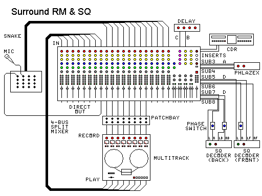
CONSTRUCTING THE CABLES
Note that if several switched or controlled devices are needed, they could be combined on a common control panel.
 RM / DS Encoder
Patch cord A. Choose the selection that best fits your mixer:
- You have built a UniQuad Phlazex. Uses standard patch cords. Set it for Encode Surround
Right-Biased.
- ENCODER INSERT jacks
- Fully balanced SUB OUT and ENCODER RETURN jacks
- Impedance balanced SUB OUT, fully balanced ENCODER RETURN
- Unbalanced SUB OUT, fully balanced ENCODER RETURN
- Unbalanced ENCODER RETURN
- You had hum problems using one of the balanced methods.
The sample illustrations in the links show 1/4 inch phone plugs. Substitute the type of connector you are
really using.
Acroperiphonic (AP) Encoder
Patch cord B. Find your AP RETURN type:
- Mono
- Tip-Ring-Sleeve stereo
- Stereo on two jacks
Patch cord C. Find your AP AUX SEND type:
- Mono
- Tip-Ring-Sleeve stereo
- Stereo on two jacks
Basic 4−Corners SQ Encoder
All of the patchcords are standard patchcords, or insert patchcords that fit the inserts and the SQ decoder. Use
the diagram on the right above:
The 4−Corners encoder is the only SQ encoder that does not need the crossfaders or two channel strips per
source.
Basic 4−Corners and Diagonal−Split−Oriented SQ Encoder
All but one of the patchcords are standard patchcords, or insert patchcords that fit the inserts and the SQ
decoder.
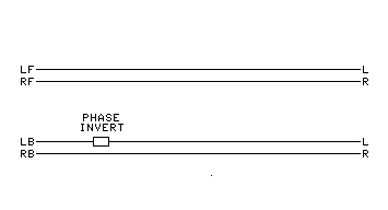
The basic phase switch is the one special cord:
- Build a custom phase reversing switch. Place it in the line for encoding the left
back.
- You have built a UniQuad Phlazex. Uses standard patch cords. Connect to both lines for
encoding SQ back.
- For the normal phase position (4−corner), set Phlazex for Stereo Pass−Through
- For the reverse phase position (forward−oriented), set Phlazex for Encode Surround Right-Biased
- The basic phase switch does not give optimum encodings of the left and right sides. It gives the optimal
diagonal splits.
Two channel strips and a crossfader are needed to encode the sides or the diagonal
splits.
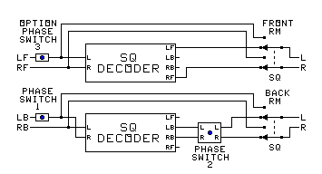
Advanced 4−Corners and Forward−Oriented SQ Encoder
The advanced phase switch is a special cord set:
- Build the advanced phase reversing switch. Place it in the lines for encoding the
left back and right back as labeled.
- The advanced phase switch changes the following abilities:
- For the forward−oriented encoder (reverse phase position), the left and right side encodings are
optimum.
- Diagonal splits are not optimum, but are usable.
- It can't be used for the RM part of the switched RM or SQ encoder. A separate phase inverter must be used.
The normal phase position selects the 4−corners encoder, and the reverse position selects the
forward−oriented encoder.
Two channel strips and a crossfader are needed to encode the sides or the diagonal
splits.
Combined 4−Corners, Diagonal Split, Forward−oriented, and Backward−Oriented SQ Encoder
The basic phase switch (1) is the one special cord. The advanced phase switch (2) is a special cord set. Both are
needed:
- Build the custom phase reversing switch. Place it in the line for encoding the left
back.
- Build the advanced phase reversing switch. Place it in the lines for encoding the
left back and right back as labeled.
- The advanced phase switch changes the following abilities:
- For the forward−oriented encoder (reverse phase position), the left and right side encodings are optimum.
Diagonal splits are not.
- It can't be used for the RM part of the switched RM or SQ encoder. A separate phase inverter must be used.
- Combined with the basic phase switch, it can produce the Backward−Oriented Encoder, if the second basic
phase switch is inserted in the front left feed line.
Two channel strips and a crossfader are needed to encode the sides or the diagonal
splits.
See the general switch table below to operate.
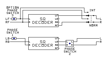
The Ultimate Encoder Pair or the switched RM / SQ Encoder
The basic phase switch (1) is a special cord. The advanced phase switch (2) is a special cord set. Both are needed,
along with a stereo source selector. A swap switch can be added for CircleSurround:
- Build the custom phase reversing switch. Place it in the line for encoding the left
feed.
- Build the advanced phase reversing switch. Place it in the lines for encoding the
left back and right back as labeled.
- The advanced phase switch changes the following abilities:
- For the forward−oriented encoder (reverse phase position), the left and right side encodings are optimum.
Diagonal splits are not.
- It can't be used for the RM part of the switched RM or SQ encoder. A separate phase inverter must be used.
- The source selector selects what kind of encoding will be done by the bus pair.
- The swap switch is used to encode CircleSurround instead of SQ.
Two channel strips and a crossfader are needed to encode the sides or the diagonal
splits.
See the general switch table below to operate.
CONNECTING THE CABLES TO THE MIXER
RM / DS Encoder

- Install the RM encoder cable (patch cord A) when not using ENCODER INSERTS:
- Plug patch cord A's LEFT SUB OUT connector into your left SUB OUT connector on the mixer.
- Plug the RIGHT SUB OUT connector into your right SUB OUT.
- Plug the LEFT ENCODER RETURN connector into the left ENCODER RETURN (with a pair of mono inputs, use the lower
channel number).
- Plug the RIGHT ENCODER RETURN connector into the right ENCODER RETURN (with a pair of mono inputs, use the
higher channel number).
- Install the RM encoder cable (patch cord A) with single-signal ENCODER INSERTS:
- Plug patch cord A's LEFT ENCODER SEND connector into your left SUB INSERT SEND connector on the mixer.
- Plug the RIGHT ENCODER SEND connector into your right SUB INSERT SEND.
- Plug the LEFT ENCODER RETURN connector into the left SUB RETURN.
- Plug the RIGHT ENCODER RETURN connector into the right SUB RETURN.
- Install the RM encoder cable (patch cord A) with tip-ring-sleeve ENCODER INSERTS:
- Plug patch cord A's LEFT ENCODER INSERT connector into your left SUB INSERT connector on the mixer.
- Plug the RIGHT ENCODER INSERT connector into your right SUB INSERT.
- When connecting a Phlazex, connect patch cables from it to the appropriate connectors on the mixer. If using TRS
inserts, you will need standard insert cables.
Acroperiphonic Encoder
To install the acroperiphonic function, make the following connections:
- Connect the mixer end(s) of patch cord B above to your AP RETURN.
- Connect the delay end(s) of the patch cord B to the OUTPUT on the digital delay.
- Connect the mixer end(s) of patch cord C to your AUX SEND.
- Connect the delay end(s) of patch cord C to the INPUT on the digital delay.
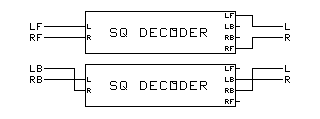
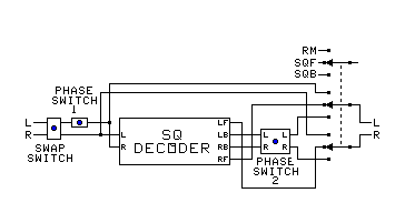
Basic SQ BACK Encoders
The SQ decoders used should NOT have logic.
Notice that the back connections to the SQ decoder are crossed. This is what turns the back channels of the
decoder into an encoder.
To install the basic SQ BACK 4−corner encoding function, make the following connections:
- Connect the odd (left) submaster bus insert send to the right SQ decoder input.
- Connect the right back SQ decoder output to the odd (left) submaster bus insert return.
- Connect the even (right) submaster bus output to the left SQ decoder input.
- Connect the left back SQ decoder output to the even (right) submaster bus insert return.
- If such an ability is provided, disable the 10−40 blend of the decoder.
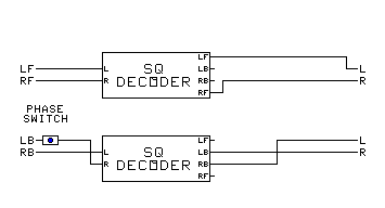
To install the basic SQ BACK 4−corner and forward−oriented encoding function, make the following
connections:
- Connect the odd (left) submaster bus insert send to the basic phase switch input or the left Phlazex input, using
a suitable cable.
- Connect the basic phase switch output or the left Phlazex output to the right SQ decoder input.
- Connect the right back SQ decoder output to the odd (left) submaster bus insert return.
- Connect the even (right) submaster bus output to the left SQ decoder input. If a Phlazex is used, insert the
Phlazex right side into this cable.
- Connect the left back SQ decoder output to the even (right) submaster bus insert return.
- If such an ability is provided, disable the 10−40 blend of the decoder.
Advanced SQ BACK Encoders
The SQ decoders used should NOT have logic.
Notice that the back connections to the SQ decoder are crossed. This is what turns the back channels of the decoder
into an encoder.
To install the advanced SQ BACK 4−corner and forward−oriented encoding function, make the following
connections:
- Connect the odd (left) submaster bus insert send to the right SQ decoder input.
- Connect the left back SQ decoder output to the odd (left) advanced phase switch input.
- Connect the odd (left) advanced phase switch output to the odd (left) submaster bus insert return.
- Connect the even (right) submaster bus output to the left SQ decoder input.
- Connect the right back SQ decoder output to the even (right) advanced phase switch input.
- Connect the even (right) advanced phase switch output to the even (right) submaster bus insert return.
- If such an ability is provided, disable the 10−40 blend of the decoder.
To install the combined SQ BACK 4−corner and forward−oriented encoding function, make the following
connections:
- Connect the odd (left) submaster bus insert send to the phase switch input or the left Phlazex input, using a
suitable cable.
- Connect the phase switch output or the left Phlazex output to the right SQ decoder input.
- Connect the left back SQ decoder output to the odd (left) advanced phase switch input.
- Connect the odd (left) advanced phase switch output to the odd (left) submaster bus insert return.
- Connect the even (right) submaster bus output to the left SQ decoder input. If a Phlazex is used, insert the
Phlazex right side into this cable.
- Connect the right back SQ decoder output to the even (right) advanced phase switch input.
- Connect the even (right) advanced phase switch output to the even (right) submaster bus insert return.
- If such an ability is provided, disable the 10−40 blend of the decoder.
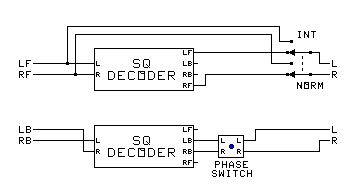
SQ FRONT Encoder
Notice that the front connections to the second SQ decoder are not crossed. The front channels do not interact.
To install the SQ FRONT encoding function, make the following connections:
- Connect the odd (left) submaster bus insert send to the left input of the second SQ decoder.
- Connect the left front SQ decoder output to the odd (left) submaster bus insert return.
- Connect the even (right) submaster bus insert send to the right input of the second SQ decoder.
- Connect the right front SQ decoder output to the even (right) submaster bus insert return.
- If such an ability is provided, disable the 10−40 blend of the decoder.
- An optional phase inverter switch can be added to the left channel to provide for SQ backward−oriented
encoding.
SQ Bypass Switches
The SQ bypass switches are the RM−SQ switches in the diagram at right.
The SQ Bypass Switches can be:
- Specially wired up switches
- Internal bypass switches in the decoders.
- Signal splitter and an off the shelf selector switch
The following table can be used for any of the SQ setups above.
If a switch is not included in your setup, its setting must be normal or SQ.
Setting the switches:
| BYPASS SWITCH TABLE |
| OPERATION |
FRONT
BYPASS
SWITCH |
BACK
BYPASS
SWITCH |
PHASE
SWITCH
1 |
PHASE
SWITCH
2 |
PHASE
SWITCH
3 |
| RM Encoder |
RM |
RM |
Reverse |
− |
Normal |
| Stereo |
RM |
RM |
Normal |
− |
Normal |
| SQ 4−Corners Encoder |
SQ |
SQ |
Normal |
Normal |
Normal |
| SQ Diagonal−Split Encoder |
SQ |
SQ |
Reverse |
Normal |
Normal |
| SQ Forward−Oriented Encoder |
SQ |
SQ |
Normal |
Reverse |
Normal |
| SQ Backward−Oriented Encoder |
SQ |
SQ |
Reverse |
Reverse |
Reverse |
| RM Acroperiphonic Encoder |
SQ |
RM |
Reverse |
− |
Normal |
| RM Alternate Acroperiphonic ‡ |
SQ |
RM |
Normal |
− |
Reverse |
| SQ Acroperiphonic Encoder |
RM |
SQ |
Normal |
Normal |
Normal |
‡ The front input buses in the setting encode back channels, and the back input buses encode front
channels.
Two channel strips and a crossfader are needed to encode the sides or the diagonal
splits.
The Ultimate Encoder Pair with CircleSurround capability:
The Ultimate Encoder Pair with the CircleSurround swap switch. Do all of the following:
- Trade the left and right decoder input lines (for the left back and right back signals).
- Put the swap switch at the mixer bus outputs.
- Add a switchable phase inverter (1) to the left source (going to the right input).
- Add a switchable phase inverter and line swap (2) to the back outputs.
- Trade the left front and right front output lines.
- Add the RM−SQF−SQB switch (can use a stereo source selector switch) as shown.
All of the various switches for the Ultimate Encoder could be put in the same box and wired together (below).
Setting the switches - If a switch is not included in your setup, its setting must be normal or SQ:
| GENERAL SWITCH TABLE |
| OPERATION |
CHANNELS |
SWAP
SWITCH |
PHASE
SWITCH
1 |
PHASE
SWITCH
2 |
MODE
SWITCH |
PAN POT
CONTROLS |
CROSS−FADE
CONTROLS |
| Stereo Pass−Through |
Stereo |
Normal |
Normal |
− |
RM |
L − F − R |
not used |
| Phased |
Normal |
Normal |
− |
SQF |
L − F − R |
not used |
| RM Encoder |
Front |
Normal |
Normal |
− |
RM |
L − LF − F − RF − R |
not used
Use Flip Buses |
| Back |
Normal |
Reverse |
− |
RM |
L −LB − B − RB − R |
| RM Acroperiphonic Encoder |
Front |
Normal |
Normal |
− |
RM |
L − LF − F − RF − R |
F − C − B |
| Back |
Normal |
Reverse |
− |
SQF |
L − LB − B − RB − R |
| SQ 4−Corners Encoder |
Front |
Normal |
Normal |
− |
SQF |
LF − F − RF |
not used
Use Flip Buses |
| Back |
Normal |
Normal |
Normal |
SQB |
LB − B − RB |
| SQ Diagonal−Split Encoder |
Front |
Normal |
Normal |
− |
SQF |
LF − F − RF |
F − Split − B |
| Back |
Normal |
Reverse |
Normal |
SQB |
LB − F − RB |
| SQ Forward−Oriented Encoder |
Front |
Normal |
Normal |
− |
SQF |
LF − F − RF |
F − Side − B |
| Back |
Normal |
Normal |
Reverse |
SQB |
LB − F − RB |
| SQ Backward−Oriented Encoder |
Front |
Normal |
Reverse |
− |
SQF |
LF − B − RF |
F − Side − B |
| Back |
Normal |
Reverse |
Reverse |
SQB |
LB − B − RB |
| SQ Acroperiphonic Encoder |
Front |
Normal |
Normal |
− |
RM |
LF − F − RF |
F − C − B |
| Back |
Normal |
Normal |
Normal |
SQB |
LB − B − RB |
| OPERATION |
CHANNELS |
SWAP
SWITCH |
PHASE
SWITCH
1 |
PHASE
SWITCH
2 |
MODE
SWITCH |
PAN POT
CONTROLS |
CROSS−FADE
CONTROLS |
| UMX Basic Encoder |
Left−Right |
Normal |
Normal |
− |
SQF |
L − C − R |
[L−R] − C − [F−B] |
| Front−Back |
Normal |
Normal |
Reverse |
SQB |
F − C − B |
| RM 3D Front Encoder |
Front |
Normal |
Normal |
− |
SQF |
L − LF − F − RF − R |
Horiz − Oblique − Vert |
| Down−Up |
Normal |
Normal |
Reverse |
SQB |
N − NF − F − ZF − Z |
| RM 3D Back Encoder |
Back |
Normal |
Reverse |
− |
SQF |
L − LB − B − RB − R |
Horiz − Oblique − Vert |
| Down−Up |
Normal |
Reverse |
Reverse |
SQB |
N − NB − B − ZB − Z |
| CircleSurround Encoder |
Front |
Normal |
Normal |
− |
SQF |
LF − F − RF |
F − Side − B |
| Back |
Swap |
Normal |
Reverse |
SQB |
LB − F − RB |
Two channel strips and a crossfader are needed to encode the sides or the diagonal
splits.
Combining the Ultimate Encoder Pair controls on a control panel
The controls for several Ultimate Encoder Pairs can be built into a common control panel.
The switches are mounted left to right on the panel in the order they are listed in the table above.
Normal positions indicate that the switches on the panel are thrown to the left.
The controls are shown set as follows:
- Subs 1 & 2: RM Fronts
- Subs 3 & 4: RM Backs
- Subs 5 & 6: SQ Forward−Oriented Fronts
- Subs 7 & 8: SQ Backward−Oriented Backs
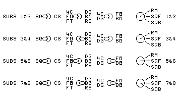
SWAP SWITCH − PHASE SWITCH 1 − PHASE SWITCH 2 − MODE SWITCH
Meanings of the abbreviations on the control panel:
- 4C − The back channels of the SQ 4−Corners Encoder
- BO − The SQ Backward−Oriented Encoder − use for both front and back
- CS − Encode CircleSurround back channels instead of SQ back channels
- DG − The SQ Diagonal Split Encoder
- FO − The SQ Forward−Oriented Encoder
- FT − Use for all front encoding except SQ Backward−Oriented
- RB − Encodes the back channels of RM
- RM − The Regular Matrix system, including Dolby Surround
- SQ − The CBS StereoQuad system
- SQB − Encode back channels of SQ and CS
- SQF − Encode front channels of SQ and CS
Output
Connect the destination (a tape recorder, CD recorder, or a surround sound decoder feeding a PA) of the encoded
surround sound to the mixer MAIN L and R outputs. Also connect a surround sound decoder so you can monitor the
results.
What happens if the SQ 10−40 blend can not be disabled?
The effects on the encoder if the SQ decoders still have their 10−40 blends:
- SQ front encoding: The pan positions are slightly moved toward the center, but not enough to cause any
trouble.
- SQ back encoding with the phase switch in the Normal Position: The pan positions are spread out slightly. Moving
the panpot inward a bit compensates. But center back encoding is also reduced in strength somewhat, requiring a
higher fader setting.
- SQ back encoding with the phase switch in the Reversed Position: The pan positions are moved forward from the
optimal LB and RB positions.
- It is usually easy to either remove the blend resistors or put them on switches so they can be disabled.
- Phlazex units can be used to completely compensate for the blend resistors. One is needed for the front, and
another for the back Connect them immediately after the decoders.
LINKS: