- You will need the following in addition to the plugs and cables:
- Two identical 600 ohm to 600 ohm audio isolation transformers
- One small plastic box to mount them in.
- Grommets or strain reliefs.
- Either a ready-made grid PC board or some solder-lug terminal strips to mount parts on.
- Remember that when you are told: "DO NOT connect the shield" That it should be trimmed off and insulated with tape or shrink tubing to prevent contact.
- Find the marking that indicates the primary winding (usually a blue or black band).
- Mark the hot phase of each winding with a magic marker such that it can be seen after the transformers are mounted. If you can't determine phase, mark the diagonally opposite terminals of both transformers. IMPORTANT! Make sure each mark is on a different winding (use an ohmmeter), and make sure both transformers marked identically.
- Cut a number of equal lengths of mic cable long enough to easily reach from your SUB OUT and ENCODER RETURN
connectors to where you plan to set the box. Leave 1 or 2 feet extra to allow for putting on the connectors,
wiring the box, extra slack, and eventual repairs. You will need:
- Four pieces if all of the jacks listed above are mono.
- Three pieces if one of the jacks listed above is stereo-tip-ring-sleeve.
- Two if all of the jacks listed above are stereo-tip-ring-sleeve.
- Make holes in the box for grommets or strain reliefs, one for each cable you just cut. Make sure they will not interfere with mounting the terminal strips, PC board, or transformers.
- If using terminal strips, mount them to the box. If using a PC board, make mounting holes, but do not mount it to the box until told to. Make sure the transformers will not obstruct the mounting holes.
- Mount the transformers to the PC board or terminal strips. Be sure the transformer is supported by its mounting lugs, not the connections. Do not mount the PC board yet.
- Connect each transformer lead to a different circuit board pad or solder lug.
- Mark one transformer LEFT and the other one RIGHT.
- Decide on a color code for hot, cold, left, and right. Wire all plugs using the same color code.
- Connect a plug that fits your ENCODER RETURN connectors to ONE end of cable lengths you just cut as follows:
- If the ENCODER RETURN jacks are balanced-line and the SUB OUT lines are balanced or are TRS, wire TWO ENCODER RETURN cables. Connect them in normal balanced-line fashion, but DO NOT connect the shields at this end.
- If the ENCODER RETURN jacks are balanced-line and the SUB OUT lines are mono unbalanced, wire TWO ENCODER RETURN cables. Connect them in normal balanced-line fashion, including connecting the shields to the sleeves.
- If the ENCODER RETURN jacks are unbalanced, wire TWO cables. Solder the hot wire to the live terminal, and solder the cold wire to the ground terminal. DO NOT connect the shields at this end.
- If the ENCODER RETURN is stereo-tip-ring-sleeve, wire ONE cable as a normal stereo cable. Solder the left wire to the tip, the right to the ring, and the shield to the sleeve.
- Mark one of the connectors you just put on as LEFT ENCODER RETURN. Mark the other as RIGHT ENCODER RETURN.
- Connect plugs that fit your SUB OUT connectors to ONE end of each of the remaining cables:
- If the SUB OUT is balanced-line, wire TWO cables. Connect them in normal balanced-line fashion. Be sure to connect the shields to the sleeves on these.
- If the SUB OUT is unbalanced and the ENCODER RETURN is mono unbalanced, wire TWO SUB OUT cables. Solder the hot wire to the live terminal, and solder both the cold wire and the shield to the ground terminal.
- If the SUB OUT is unbalanced and the ENCODER RETURN is balanced or TRS, wire TWO SUB OUT cables. Solder the hot wire to the live terminal, and solder the cold wire to the ground terminal. DO NOT connect the shields at this end.
- If the SUB OUT is stereo-tip-ring-sleeve, wire ONE cable as a normal stereo cable. Solder the left wire to the tip, the right to the ring, and the shield to the sleeve.
- Mark one of the connectors you just put on as LEFT SUB OUT. Mark the other as RIGHT SUB OUT.
- Install the grommets, if used. Do not install any strain reliefs yet.
- Push the free ends of the wires into the proper holes in the box made to receive them.
- Connect the ENCODER RETURN cables as follows:
- If the ENCODER RETURN plugs are mono, connect each cable to its marked transformer:
- Solder the hot wire to the secondary hot terminal.
- Solder the cold wire to the secondary cold terminal.
- Connect the shield to the transformer case pin.
- If the ENCODER RETURN is a stereo cable:
- Solder the left hot wire to the left secondary hot terminal.
- Solder the right hot wire to the right secondary hot terminal.
- Solder the shield to one of the secondary cold terminals.
- Solder a jumper wire from there to the other secondary cold terminal.
- If the SUB OUT is mono unbalanced, connect a jumper from one secondary cold terminal (on ENCODER RETURN) to the transformer case.
- If the ENCODER RETURN plugs are mono, connect each cable to its marked transformer:
- Connect the SUB OUT cables as follows:
- If the SUB OUT plugs are mono:
- Connect the right cable to its marked transformer first:
- Solder the hot wire to the right primary hot terminal.
- Solder the cold wire to the right primary cold terminal.
- Solder the shield to the transformer case pin.
- Now connect the left cable to its transformer (here's the tricky part):
- Solder the HOT wire to the left primary COLD terminal.
- Solder the COLD wire to the right primary HOT terminal.
- Solder the shield to the transformer case pin.
- Connect the right cable to its marked transformer first:
- If the SUB OUT is a stereo cable:
- Solder the left HOT wire to the left primary COLD terminal (the tricky part).
- Solder the right HOT wire to the right secondary's HOT terminal.
- Solder the shield to one of the transformer's case pins.
- Solder a jumper wire from that transformer's case pin to the case pin on the other transformer.
- Solder a jumper wire from the right transformer case pin to the right primary COLD terminal.
- Solder a jumper wire from the left transformer case pin to the left primary HOT terminal (tricky part 2).
- If the SUB OUT plugs are mono:
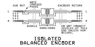
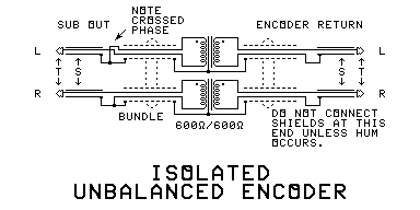
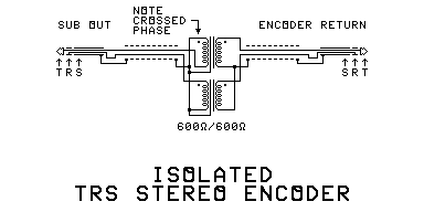
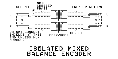
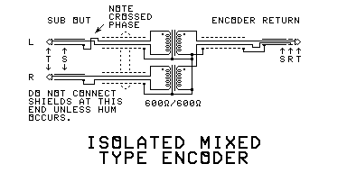
- Select the correct diagram for your mixer from this page, and compare it with the wiring you actually did, to make sure your wiring is correct. Correct any mistakes.
- Use an ohmmeter to make sure that parts that are not supposed to be connected together are isolated from each other. Also check across the transformer windings to make sure they have not been shorted out. A short gives a reading of 0, an open gives a reading of infinity (or very high megohms). The winding should give a reading which is somewhere in between - usually in the range of 50 ohms to 10000 ohms.
- Mount the PC board, if used.
- Install the strain reliefs, if used.
- Install the box cover.