I had an idea for putting three channels in a record groove. But the speaker location I envisioned was centered high over the center of the regular stereo pair. I intended a phono cartridge sensitive to different vertical angles for the high channel and the others. I now know that this would have produced distortion.
I also had a brief thought of channels at other angles in the same plane the left and right channels are recorded in, but dropped it because it would crosstalk. This was essentially RM.
In 1968, I came across a stereo system with a center channel amplifier and speaker. The center channel was the vector sum of the left and the right channel, corresponding to the modulation of a mono record.
- c = .71L + .71R
This is an example of three channels being decoded from two - a matrix system.
In 1968, I found an article in a magazine 0 on how to build a speaker set for stereo with five speakers like the set placed behind the movie screen in Cinerama. The signals to the speakers were:
- Left: l = L
- Left-Center: lc = .92L + .38R
- Center: c = .71L + .71R
- Right-Center: rc = .92R + .38L
- Right: r = R
This is an example of five channels being decoded from two - a matrix system.
This 1969 article was the first one I ever saw on 4-channel stereo. 0 It described a method of using 4 tracks on tape to record a concert, including the ambient sounds of the concert hall. I later found out from an email I received that Pink Floyd had made 4-channel live concerts that same year.
At that time, I had thought that 4 channels would be the end of my favorite recording medium, the phonograph record (and my associated favorite, the record changer). But near the end of 1969, I heard of a system called the Scheiber system (invented by Peter Scheiber "shee-ber") that could put 4 channels in a single record groove. 0 This was worth investigating.
Record companies started making discrete quadrasonic reel-to-reel tapes (R4) in 1969 and eight-track quadrasonic tapes (Q8) the following year. But the tapes were not compatible. They would not play on standard players without losing half of the sound.
I thought at the time that a totally incompatible system would not sell. I didn't find out until years later that I was right, because reel-to-reel quadrasonic recorder sales exceeded projected expectations. See below to find out why this happened.
Record companies wanted to make discrete quadrasonic cassette tapes. They wanted to use all 4 tracks at once (C4) in the same direction. But Philips, holder of the patents on the cassette, said that such a tape violated their licensing agreement. That agreement requires stereo and mono (and other formats) to be able to play each other's formats while the user hears all of the music that goes together.
The C4 format violates the agreement - half of the tracks would not be played in stereo or mono. Philips suggested eight-track quadrasonic tapes (C8) to maintain compatibility. The problem is that such a narrow track would lose fidelity and increase crosstalk.
This was not achieved other than in a lab during the times of 4-channel. I now have a TASCAM 8-track cassette multitrack recorder, but the even tracks are offset from the odd tracks, so it is not compatible with stereo or mono tapes.
By July of 1970, I had much more information than what I knew in 1969. More articles had been published on the various systems, and I had taken some mathematics and electronics courses necessary to understanding the various systems:
-
Information on the original Hafler-Dynaco diamond system, including the matrix math: 1 This system put one speaker in front, one speaker on each side, and one in the back (differing from the 4-corners of the room used by other systems). The front speaker has the sum (L+R) signal, while the back speaker has the difference (L−R) signal. This system was unique, because it needed only one stereo amplifier to operate all 4 speakers.
The diagram here (right) shows the stylus motions for each signal in the Hafler system. Each straight line is the angle of the stylus vibration the record groove imparts to the stylus as seen from the cartridge end of the pickup arm (ignore the circular stylus motions in the diagram - they were not added until 1978).
Hafler
Right-click on the diagram and select "View Image" to see a larger version. Note that the arrows show the relative phase, and that the violet arrow is backward for the Hafler System. The diagram is used several times on this page, but the arrowhead belongs on the other end for only the Hafler system.
The circles in these first three diagrams should appear to be perfect circles. If they appear to be elliptical, check the aspect-ratio and height/width settings of your monitor. They should print as perfect circles too. But note that some 5:4 flat screen monitors can't have the correct aspect ratio at a resolution that is easy to see.
- Information on Jerry Minter's 1953 attempt to make stereo records using an FM radio frequency carrier in the record groove: The Minter system would have required a very fragile record groove and a special playback stylus. It was abandoned when the Westrex 45/45 system was adopted in 1957 for recording stereo in one record groove. 0 But Minter was back with his system in 1969 for quadraphonic use.
- More information on the Scheiber system: It was said to be a system of encoding 4 channels of sound into 2 channels. 2 This is to be used for records, tapes, and FM stereo broadcasts. The system then recovers 4 channels to send them to speakers. The details had not yet been revealed.
- The knowledge of trigonometry and complex numbers gained from taking an advanced math course
-
The knowledge of the use of trigonometry and complex numbers for phase angle in electronic circuits gained from an electronics course.
Sketch 1 - 90°
Sketch 2 - Carrier
Sketch 3 - 22.5°
- The knowledge of how to make phase shift circuitry that works over large frequency ranges
- Knowing how records are cut and tapes are recorded
After reading the article on the Hafler system, I sat down with a clipboard and quickly sketched out what I thought were the three most likely possibilities for the Scheiber system:
- My first sketch was a system where the front channels were encoded on the record in the normal way, and the back channels were encoded using 90 degree phase shifts that produced circular stylus motions (Sketch 1 - right). I rejected it as having too much front-to-back crosstalk for use with recordings of concert-hall ambiance. But it would work with records, tape, and stereo FM.
- My second sketch (Sketch 2- right) was a variation of Jerry Minter's FM system for a stereo record combined with the Westrex 45/45 stereo groove. But since it would not work with tape or FM stereo, it was definitely not the Scheiber system. I also rejected it because the groove would be very fragile, that it would require a special playback stylus, and that it could not be slip-cued without making a swooping sound.
- My third sketch was a system which had modulations spaced 45° apart in the stereo
groove, instead of the usual 90° spacing (Sketch 3 - right). The front modulations were 22.5 °
from the horizontal (mono) modulation, and the back modulations were 22.5 ° from
vertical. It was essentially the Hafler system rotated by 45° in the room and 22.5°
in the record groove. It was a system that could be used for records, tape, and FM stereo.
I decided that this was probably the correct guess.
I still have those sketches, all on one piece of notebook paper. Together they took about half an hour to draw.
It is amazing how prophetic those three little sketches were:
- My first sketch turned out to be the CBS SQ system, written down by me before CBS had even thought of it. But at the time, I thought it had no practical use for recording concert-hall ambiance, because of the low front-back separation and nonexistent separation between center front and center back.
-
My second sketch turned out to be CD-4. Unknown to me, It was being developed by JVC in secret at the time I drew the sketch.
Again, I thought at the time that it would be too difficult to use. I was right about that too, as seemingly insignificant events showed me the fragility of the system. Radio DJs had discovered they could not slip-cue the Minter records back in the '50s without making a swooping squeak when the record started turning. The blank groove is not blank.
-
My third sketch turned out to really be the Scheiber system. I found out in September of that same year that I was right (see below). The encoding and decoding equations were published then.
It was also the QS system, being developed by Sansui at the time I made the sketches. I found out about it the following year. It is also related to the Electro-Voice and Dynaquad systems (see below).
Wow!
I had just sketched out the three main competing quadraphonic systems of the future
within a half-hour period in July 1970.
But I wouldn't know that until late 1971.
In 1970, marketing people and writers were trying to decide what to call four-channel sound. Here is a list of some of the suggestions and comments about them:
- Quadrasonic - hard to pronounce
- Quad - already trademarked for speakers, so it could not name four-channel sound. But it was used in unofficial speech anyway.
- Four-channel sound - too wordy
- Fourchan - hard to say, and was already trademarked.
- Tetrasonic - too esoteric
- Tetraphonic - too esoteric
- Four-way sound - multiple meanings
- Four-way stereo - multiple meanings
- Four-speaker stereo - too wordy
- Quadraphonic - used until 1979
- Surround Sound - used after 1980
Quadraphonic was chosen by record stores by 1972.
There is also still some confusion between discrete (separated) and discreet (tactful). Will someone please write a screed about it?
In September 1970, the details of the Scheiber system were revealed. 3 It was the matrix I outlined above, with a gain-riding system to turn down the speakers that had only crosstalk. This gain riding system was easily fooled, and often drowned out hall ambience.
In my opinion, the Scheiber system was never put into production because each record company was hoping to develop its own system to avoid paying patent royalties. But Scheiber collected anyway, because his patent covered ALL matrix encoding/decoding systems (Note that all of the quadraphonic patents have expired by 2012).
But even though his system was never used by any recording company, Scheiber still deserves the credit for inventing the concept of matrix quadraphonic recording and playback.
In the summer of 1970, I sketched out other possibilities for discrete quadraphonic records:
- My first sketch was an expansion of the Cook dual groove system (right), but with the grooves next to each other, rather than in separate bands on the record. But the shortened playing time and the difficulty of starting the record playing in the middle of a selection were sufficient disadvantages to this system.
- The second sketch was a two-level groove with two styli of different sizes, one above the other in the same groove. This could not have worked, because one level moving in one direction while the other level moved in the other direction would cause problems in the groove. The playing level would also be a lot lower.
- I also had the idea of using grooves on both sides of a record together. This had the same troubles the dual groove system had.
None of these would have been viable. They were just some wild ideas I had jotted down. But RCA did have a patent on a dual-groove system. All of them reduce playing time of the record and none of them would play on a standard player.
In 1970, the Geluk system for phonograph records was announced. It was a stereo record with an ultrasonic control tone added that controls pan pots to change the direction the sound comes from. This idea worked for Cinerama, but is not a good idea for music. And it would cause the same trouble with DJ slip-cueing.
Utah made a speaker matrix device that made fake 4-channel from the sum and difference signals. The front left and front right speakers get the left and right channels from the stereo signal. The left back gets the sum of the two stereo channels, while the right back gets the difference of the two stereo channels. This was useless in its intended form, but could be used to implement the Hafler diamond by putting the left back speaker in the center front.
The Denon QX system was a commercially sold version of their Dual Triphonic system that used 5 speakers. It was essentially equivalent to the Dynaco 5 speaker version of Dynaquad.
4 channels
6 channels
In August 1970, I built an adaptor from a block of 6 RCA jacks, a resistor, and a rheostat (right) to connect to a friend's stereo set that had speakers connected by RCA cables. He had used Y adaptors to connect two more speakers to the stereo, with one speaker on each wall of a square room. I replaced that arrangement with the Hafler diamond.
The rheostat is adjusted to minimize left channel sound in the right speaker and right channel sound in the left speaker. It compensates the front speaker load.
We spent some time listening to stereo records with this setup, and for the first time heard the stereo enhancement effect of matrix quadraphonics and the recovery of hidden ambience in live recordings. Right then, I knew I never again would be content with ordinary stereo.
I discovered one stereo recording where the stereo channels were recorded out of phase with each other. The instruments intended to be between the stereo speakers were in the back speaker instead of the front. Unfortunately, the record belonged to someone else, and I have forgotten what record it was. It was classical.
Later I built an adaptor with a block of 8 RCA jacks (right) that would hook up six speakers: four using the Hafler connection, plus two more speakers hooked up as normal stereo speakers - a hexaphonic system. We got to play with it for only an hour, because I had borrowed speakers to set it up and the owner wanted them back. But the sound images of the musical parts were more stable than the images with the 4-channel setups were. This system needed no adjustment.
I later discovered that this hexaphonic system was nearly identical to the Denon Dual Triphonic system.
I also sketched out an octophonic system, but never got to try the idea until 2010.
Both of these circuits can be built with screw terminals instead of RCA jacks. Be sure to observe polarity.
3 channels
 Since I had only 3 good speakers that I actually owned, I hooked up a
"tristereo" system that was essentially the Dynaco Diamond with no
front center speaker. I used it until I had enough money to buy 4 identical
speakers.
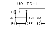
The diagram on the left uses RCA-plug speaker cables. The diagram
on the right uses an amp with screw terminals. The wire connecting the (-)
terminals is not needed if the amp provides it internally.
I used this setup to monitor the recordings I made in the next item.
When I got the 4 identical speakers, I used the Tristereo with both back
speakers connected in parallel
until I had built the UQ-1 (below). The speakers were put on milk crates to
raise them closer to ear level
and so occasional water on the floor from a high water table would not damage
them.
This started with a friend coming to me with this question: "Is there any way to easily synchronize 5 tape recorders?" They wanted to place sound effects around the audience of a live theater production. The play was "Ondine", and they wanted to make the voices of ghosts, beings, and other sound effects come from different directions in the auditorium.
I told him that it would be easier to use one stereo tape recorder with multiple speakers and the Hafler 4-channel system.
We wired the system to speakers placed on a catwalk that circled the rim of the auditorium above the audience. I used a small stereo mixer and a preamplifier that had two sets of outputs reversed in phase to each other to encode the recordings.
My concept of using a mixer to encode was born.
We had the ghostly voices coming from various directions, thunder rolling across the auditorium, and other sound effects placed over the stage to match events on the stage. The cues were separated with leader tape, so the tape was started for each cue and stopped between cues.
The play took place in early 1971. The sound effects were quite effective. I believe it was the very first use of matrix quadraphonics in a live theater presentation.
Unfortunately, since the sound tapes belonged to the school, I have no recordings of this event. I don't even have the auditorium to show where it happened anymore - it was torn down to build a computer building.
See a detailed account of this at Quadraphonic Mixing a 1971 Stage Play
Later in 1971, I acquired the following materials and information:
- I sent away for a demonstration record of the Electro-Voice Stereo-4 system (Ovation Records). It contains various kinds of music, as well as a calibration track and sound effects.
- Dynaco sent me information about the Dynaquad system. It is a modification of the Hafler diamond system that allows placing the speakers in the corners of the room (instead of on the centers of the walls). The package also contained a schematic on how to set up this new system, and the Dynaco "4-Dimensional Demonstration Disc", an album encoded in the Dynaquad system. The record has a classical side and a popular side.
- Sansui sent me a complete description of the workings of the Sansui QS system. 4
- I found in various magazines the encoding and decoding coefficients for the Stereo-4, QS, and Dynaquad systems. 0 Leonard Feldman later wrote a book containing the coefficients of most matrix systems and an account of how he and Jon Fixler created Stereo-4 from experimenting with how to use headphones with 4 channels. 18
- Other magazines contained information on the Denon Triphonic 3-channel and Dual-Triphonic 5-channel and 6-channel systems. 0 They were sold under the name QX (these were variations on the Hafler diamond that used multiple speakers instead of interconnecting speakers to matrix them).
- An article0 said that both Electro-Voice and Denon were experimenting with ceramic pickups with supercardioid response patterns to increase separation between channels on a phonograph record. It didn't work because it just redistributed the crosstalk without removing it. It would have also required 8-lead phono pickup wiring.
I experimented with the Dynaquad circuit, using it with the Stereo-4 and Dynaquad records:
- I realized that matrix quadraphonics could work quite well without front-back encode and decode symmetry. In fact, it worked very well.
- The Stereo-4 and Dynaquad systems seemed to be very similar to each
other - so similar that the average listener could not tell the two kinds of recordings
apart.
(The only difference between the encoding equations is that the front channels are encoded farther apart in Dynaquad.) 18
- Tuba Mirum from the Berlioz "Requiem" is on the Dynaco record.
For the first time, it could be heard at home as it was intended to be
performed, with choirs both in front of and behind the audience. The Dynaquad hookup did
a splendid job with this.
(Note: This is not a tuba composition. "Tuba Mirum" is Latin for "Wonderful Trumpet". The Latin word "Tuba" means "Trumpet".)
Electro-Voice made stereo and mono phono pickup cartridges for many years. Their idea was to design one that increased the separation between the channels of a matrix system.
Apparently it did not work without producing distortion. We never heard about it again.
I used a variation of the Dynaquad system connected to the speaker outputs of a stereo jukebox. It used essentially the Stereo-4 decoding parameters.
Later, Seeburg made quad decoders for its jukeboxes which were similar to Dynaquad. Many record companies released special Dynaquad records marked "Quadraphonic" to be played on them.
I built a variable separation decoder that works in a manner similar to the Dynaquad. I called it the UniQuad UQ-1, and used it to investigate the effects of changes in matrix parameters, as well as for listening to music on a daily basis from late 1971 to 1974. I still have two UQ-1 and two UQ-1A units (including the original). Two of these are still in service.
The UQ-1 (right) has the basic circuit in the UQ-1A. Follow the link to see the UQ-1A plans. The UQ-1 differs from the UQ-1A in the following ways:
- The original UQ-1 Width and Depth control 50-ohm 10 watt rheostats became unavailable without a special production run order, so UQ-1A uses available 8-ohm L-pads instead.
- UQ-1 does not have the LF & RF channels level control.
- UQ-1 does not have the center and subwoofer channels.
- UQ-1 does not have the Filter.
- UQ-1 does not have the Autovary function.
Using the width and depth controls, I was able to vary the matrix playback parameters to emulate any of what would eventually be called the Regular Matrix (RM and QM) systems (Scheiber, Stereo-4, Dynaquad, and QS). In doing so, I discovered the properties of the various matrix systems and found which was optimum for each kind of music.
This was even more effective with the Berlioz "Requiem". The two choirs were more definitely located using either the Stereo-4 settings or the QS settings.
I also discovered the inability of human hearing to correctly locate sounds panned directly to the sides of the room when the speakers are placed in the corners of the room and the listener is facing forward (see below).
I formed the thought that separation between the back speakers is not nearly as important as the separation between the front and the back and the separation between the front speakers. This was especially true when the recording was of classical music with concert hall ambiance recorded in the back speakers.
I independently discovered the inability of human hearing to correctly locate sounds positioned directly to the sides when the speakers are located in the corners of the room and the listener is in the proper place facing forward. I had to turn my head to hear them.
Here are the angles of the speakers from the listener at three different listener locations (note that the original encoding angles are the angles in the left diagram):
| 315.0° | 0.0° | 45.0° | 326.3° | 0.0° | 33.7° | 333.4° | 0.0° | 26.6° |
Recording made using angles in left diagram. Key to table below:
|
|||
| 270.0° |  |
90.0° | 296.6° | |
63.4° | 315.0° | 45.0° | |||||
| 225.0° | 180.0° | 135.0° | 243.4° | 116.6° | 270.0° | |
90.0° |
The human hearing system behaves as follows when listening to a single pan-potted discrete quadraphonic musical part. Note that the angles are shown on the right side of the listener in the following table. The same angles also happen in opposite directions on the left side.
| Recorded location |
Perceived locations | |||||
|---|---|---|---|---|---|---|
| Listener is in Center of Room | Listener Halfway Back in Room | Listener Between Back Speakers | ||||
| Direction | Result | Direction | Result | Direction | Result | |
| 0.0° | 0.0° | Good | 0.0° | Good | 0.0° | Good |
| 22.5° | 22.5° | Good | 18.4° | Good | 14.0° | Good |
| 45.0° | 45.0° | Good | 33.7° | Good | 26.6° | Good |
| 67.5° | 45.0° | Poor | 41.5° | Fair | 33.7° | Good |
| 90.0° | 45.0 ## 135.0° | Bad | 116.0° | Poor | 45.0° | Good |
| 112.5° | 135.0° | Poor | 116.0° | Poor | 63.4° | Good |
| 135.0° | 135.0° | Good | 116.0° | Good | 90.0° | Good |
| 157.5° | 165.0° | Good | 145.0° | Good | 90.0° | Good |
| 157.5° † | 157.5° † | Good | 135.0° † | Good | 135.0° † | Good |
| 180.0° | 180.0° | Poor | 180.0° | Poor | Centered | Poor |
| 180.0° † | 180.0° † | Good | 180.0° † | Good | 180.0° † | Good |
| Centered | 0.0° ## 180.0° | Bad | 0.0° | Fair | 0.0° | Fair |
- Panning actually works for sounds panned between stereo speakers front of the listener.
- Panning does not work for sounds placed between speakers on one side of the listener.
- Panning works, but not very well, with sounds placed between the two back speakers.
- The listener has to turn his head to hear sounds from the sides in their proper locations. But I noticed that this locating error was not there with the Hafler diamond system when the listener faces forward. All of the panning was heard with left-right hearing.
This is what the listener really hears.
| 315.0° | 0.0° | 45.0° | 326.3° | 0.0° | 33.7° | 333.4° | 0.0° | 26.6° |
Key:
|
|||
| ## | |
## | ## | |
## | 315.0° | 45.0° | |||||
| 225.0° | ## | 135.0° | 243.4° | 116.6° | 270.0° | |
90.0° | |||||
| 225.0°† | 180.0°† | 135.0°† | 243.4°† | 180.0°† | 116.6°† | 270.0°† | 180.0°† | 90.0°† |
Note that even the discrete systems do not form the correct sound images. The sound tends to jump to one speaker or the other, especially at the sides to the left and right of the listener.
Hugh Robjohns in his article "Surround Sound Explained" called this effect "puddles of sound at the speakers". 26
When a sound image is panned along the side of the listener, the image seems to "cog" between speaker locations instead of appearing to move smoothly between the speakers. The listener's head must turn to one side to hear smooth panning between side speakers properly.
The more speakers in a discrete system, the more places the sound can cog to.
A better way of locating sound images is needed for both discrete and matrix systems. Attempts to do this are called Cog Removal Attempts.
Early in the development of matrix quadraphonics, one problem was the "out of phase hole in the back" predicted by the encoding and decoding equations. It was mentioned by several authors in various audio articles. 0 This was usually between the back speakers, but with the Hafler diamond system, it was between the right speaker and the back speaker.
It was not the problem the math predicted it to be:
- In the case of the playback through speakers, it has not been the problem that was anticipated. In cases where the back signals come out of the back speakers out of phase, the phase difference actually aids a listener facing forward to correctly locate the sound.
- The worst case occurs when a 4-channel tape that had already been mixed for discrete playback is run through the "standard encoder" the matrix equations were written for. With all of the matrix systems discussed so far (except the QS encoder), anything on the tape that is panned between the back speakers is greatly attenuated, and appears between the two front speakers.
- The encoding problem is avoided by using a mixer to encode. Since the equations are not all invoked simultaneously on the same signal, each part can be panned exactly where it belongs in the mix (instead of being constrained to the defined encoding equations). Thus it appears exactly where the sound engineer wants it to appear. The engineer listens through the proper decoder to position each sound.
- The encoding hole cannot be removed, but it can be moved. All matrix systems have at least one hole. But by adjusting the encoding equations, the hole can be moved. It can also be divided into two smaller half-holes with smaller image errors (QS does this 4 ).
- When using a mixer as the encoder, each channel strip can have its own movable hole.
- There are also compatibility problems between these systems and the normal stereo and
mono methods of playing records and broadcasting:
- When played in mono, all of the quadraphonic systems I mentioned so far cause sounds panned to the back to be diminished in level. Sounds panned directly behind the listener entirely disappear in mono playback.
- This also happens when the record is played on a stereo radio station and the listener has a mono radio.
- QS recordings can be played in mono with no losses by mixing the 4 outputs of a basic QS decoder together before playing or broadcasting the signal. No other matrix system can do this.
In the summer of 1971, I did the calculations for the matrices I then knew about, and created a table showing how well each system would work with various kinds of music. This is a condensation of that table:
| System | Quadraphonic Separation | Stereo Synth Separation | Center Back − Mono ¤ |
Music Performance | Original Hole Locations |
|||||||||
|---|---|---|---|---|---|---|---|---|---|---|---|---|---|---|
| Front | Back | Sides | Front | Back | Mono- Back |
Hall Amb | Pop Mix |
Live Band | Stereo Synth | Mono play ¤ |
Side Image |
|||
| Scheiber | 3.0 dB | 3.0 dB | 3.0 dB | 8.3 dB | 8.3 dB | 8.3 dB | 40 dB | Fair | Good | Good | Good | Bad | Blur | Center Back |
| Hafler (3 speaker) | 25 dB | 0.0 dB | 3.0 dB | 25 dB | 0.0 dB | 25 dB | 40 dB | Good | Good | Good | Good | Bad | Blur | Right Back |
| Hafler (4 speaker) | 25 dB | 0.0 dB | 3.0 dB | 25 dB | 0.0 dB | 25 dB | 40 dB | Good | Good | Good | Good | Bad | Good | Right Back |
| E-V Stereo-4 | 8.3 dB | 0.2 dB | 4.9 dB | 14 dB | 4.1 dB | 19 dB | 40 dB | Better | Good | Good | Better | Bad | Blur | Center Back |
| Dynaquad | 25 dB | 1.2 dB | 1.2 dB | 25 dB | 4.8 dB | 12 dB | 40 dB | Fair | Fair | Fair | Good | Bad | Blur | Center Back |
| Sansui QS | 3.0 dB | 3.0 dB | 3.0 dB | 8.3 dB | 8.3 dB | 8.3 dB | 40 dB | Fair | Good | Good | Good | Bad ◊ | Blur | Both Sides |
| Hall Ambience | 3.0 dB | 0.0 dB | 8.3 dB | 8.3 dB | 3.0 dB | 25 dB | 40 dB | Best | Poor | Good | Good | Bad | Blur | Center Back |
¤ This is how each system plays on a normal mono player.
◊ This system provides best mono play by equally mixing decoder outputs.
Blur indicates that turning the head is needed to hear side images.
The Hall Ambience system was my own idea of finding a way to maximize concert-hall ambience. I set the UQ-1 Width control for QS, and the Depth control for maximum depth (no back separation). It does work better than playback using any of the standard matrix parameters. Encoding would be done with a QS encoder with nothing but hall ambience fed to the back channels. Several Vox classical albums are recorded in QS in this way.
The following separations are critical to the quality of concert hall ambience:
| System | Separations to LB | Separations to CB | .. | Ambience Worst Case | |||||||||||
|---|---|---|---|---|---|---|---|---|---|---|---|---|---|---|---|
| Pan LF | 22.5° L | Pan CF | 22.5° R | Pan RF | Pan LF | 22.5° L | Pan CF | 22.5° R | Pan RF | Wd LB | Wd CB | Nr LB | Nr CB | ||
| Scheiber | 3.0 dB | 5.1 dB | 8.3 dB | 14.2 dB | 40.0 dB | 8.3 dB | 14.2 dB | 40.0 dB | 14.2 dB | 8.3 dB | 3.0 dB | 8.3 dB | 5.1 dB | 14.2 dB | |
| Hafler (3 spkr) | 8.3 dB | 14.2 dB | 40.0 dB | 14.2 dB | 8.3 dB | 8.3 dB | 14.2 dB | ||||||||
| Hafler (4 spkr) | 8.3 dB | 14.2 dB | 40.0 dB | 14.2 dB | 8.3 dB | 8.3 dB | 14.2 dB | ||||||||
| E-V Stereo-4 | 4.9 dB | 10.1 dB | 19.0 dB | 11.2 dB | 5.3 dB | 5.1 dB | 10.7 dB | 40.0 dB | 10.7 dB | 5.1 dB | 4.9 dB | 5.1 dB | 10.1 dB | 10.7 dB | |
| Dynaquad | 1.2 dB | 4.3 dB | 11.7 dB | 17.7 dB | 6.0 dB | 3.0 dB | 8.3 dB | 40.0 dB | 8.3 dB | 3.0 dB | 1.2 dB | 3.0 dB | 4.3 dB | 8.3 dB | |
| Sansui QS | 3.0 dB | 5.1 dB | 8.3 dB | 14.2 dB | 40.0 dB | 8.3 dB | 14.2 dB | 40.0 dB | 14.2 dB | 8.3 dB | 3.0 dB | 8.3 dB | 5.1 dB | 14.2 dB | |
| Discrete Tape ‡ | 30.0 dB | 30.0 dB | 30.0 dB | 30.0 dB | 30.0 dB | 30.0 dB | 30.0 dB | 30.0 dB | 30.0 dB | 30.0 dB | 30.0 dB | 30.0 dB | 30.0 dB | 30.0 dB | |
| Hall Ambience | 8.3 dB | 14.2 dB | 40.0 dB | 14.2 dB | 8.3 dB | 8.3 dB | 14.2 dB | 40.0 dB | 14.2 dB | 8.3 dB | 8.3 dB | 8.3 dB | 14.2 dB | 14.2 dB | |
Notes:
- The Hafler systems do not have LB and RB speakers.
- Wd = The orchestra is recorded wide, between the LF and the RF speakers.
- Nr = The orchestra is recorded narrow, restricted to 22.5° on each side of CF.
- LF, CF, and RF are either real speakers or phantom images when no speaker is there.
- ‡ Not a matrix system. Separations don't depend on location.
RM - equal angles
QM - wider front
The Japan Phonograph Record Association (JPRA) issued an industry standard defined as "Regular Matrix" (RM) in 1971. It includes the equal separation matrix systems I mentioned so far (the Scheiber, Hafler diamond, and QS systems).
The Japan Phonograph Record Association (JPRA) also issued an industry standard defined as "Quadraphonic Matrix" (QM) in 1971. It includes the front-oriented matrix systems I mentioned so far (Stereo-4, Dynaquad, and QX).
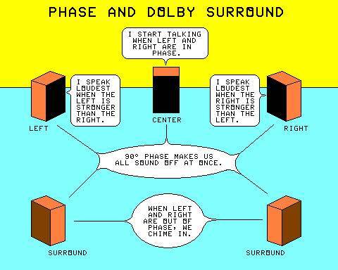
The RM and QM standards state that leftness and rightness are determined by the relative strengths of the left and right channels in the encoded recording, and that frontness and backness are determined by the relative phase between the channels. Front sounds are recorded in both stereo channels with the signals in phase with each other, and back sounds are recorded in both stereo channels with the signals in opposite (180°) phase.
The difference between RM and QM is in the separations between the channels. RM has equal separations all around (between front channels, between back channels and between adjacent front and back channels) and infinite diagonal separation. QM has greater separations between front channels and often between adjacent front and back channels, but lower separation between back channels and diagonally. RM places a sound recorded in just the left channel of a stereo record to the middle of the left side. QM moves it close to the left front. Sounds on the right are similarly placed.
The upper diagram at the right shows the basic modulations of the RM system as stylus motions. Notice the even spacing. Right-click on it and select "View Image" to see a larger version.
The lower diagram at the right shows the basic modulations of a QM system as stylus motions. Notice the wider spacing of front signals and the narrower spacing of back signals.
The circular motions indicated in brown or black are not part of the RM standard. Of the early RM matrix systems, none used the circular motion except QS. The QS encoder produces the black clockwise circular motion when the same signal is panned equally to all 4 channels (placed at the center of the room). It does not produce the brown motion. The QS decoder properly locates the black circular motion in the center of the room.
The Electronic Industry Association of Japan (EIAJ) also issued an RM standard and a QM standard.
The encoding parameters of all of the RM and QM systems are so close together that the records are nearly indistinguishable from each other. The main differences between these RM and QM systems are in the decoders and speaker placements.
Up to this point, all matrix systems already proposed (Scheiber, Hafler, Stereo-4, Dynaquad, Dynaco Diamond, and QS - collectively RM/QM) were almost identical. Recordings made in these systems were interchangeable, with only slight shifting in sound images. It looked like the matrix race was over before it had begun. But that was soon to change.
In July 1971, Columbia and CBS announced a matrix system with totally different properties - the Stereo-Quadraphonic (SQ) matrix. 5, 7 It works on a somewhat different principle than the regular matrix. But it is identical to that first sketch I made in July of 1970. The diagram at right shows the ideal SQ modulations.
The SQ system was designed as a result of a directive from Columbia corporate headquarters. It said that any quadraphonic system used by Columbia must have full separation between the left-front and right-front channels in stereo and in quadraphonic play. This removed from consideration the RM systems and the "New Orleans" systems they had been trying out before (see below).
It also prevented SQ from being seriously used for recording concert-hall ambience. The ambience must be recorded at a higher level to be heard with SQ, and at even a higher level to get it past the early gain-riding separation-enhancement systems used.
Before the directive, the CBS labs were investigating systems similar to QS and BMX (but before either of those systems were revealed) in New Orleans LA. They referred to these systems as the "New Orleans" matrix systems in an article published about the development of SQ. 10
SQ as defined
SQ 10-40 blend
SQ has the following signals (see upper diagram at right):
- The left front signal is the normal stereo left channel (dark green line).
- The right front signal is the normal stereo right channel (yellow line).
- The left back signal is a clockwise circular stylus motion* (blue circle).
- The right back signal is an anticlockwise circular stylus motion* (magenta circle).
- The center front signal is the normal stereo center channel (yellow-green line).
- The center back signal is a vertical stylus motion (violet line).
* Rotations are as seen from front of the pickup cartridge. Both circles are concentric, and are easier to see if you right-click on it and select "View Image" to see a larger version.
The JPRA issued an industry standard defined as "Phase Matrix" (PM, also known as SQ) in 1971. It includes the SQ and Electro-Voice Universal systems (below). The EIAJ also issued such a standard.
The SQ system was designed to be used with separation-enhancement circuitry. If separation enhancement is not used with a cheaper decoder, CBS advises that a 10% blend between the front decoder outputs and a 40% blend between the back decoder outputs be used to provide more separation between center front and center back.
This is called the 10-40 SQ decoder (suggests paying taxes). See the stylus-motion diagram of 10-40 SQ playback at right. Note the horizontal orientation of front material and the vertical orientation of back material.
This somewhat improves the ability to handle ambience, but it is not as good as any of the RM or QM systems except Dynaquad. It also lets the 10-40 SQ decoder play RM and QM recordings.
The separation-enhancement circuitry originally used gain-riding techniques to emphasize either the front channels or the back channels. It detects cases where program material is either predominately front or predominately back, and adjusts the gains appropriately. Their original gain-riding system was easily fooled by program material, and often turned down concert-hall ambience while increasing separation.
Without either the 10-40 blends or the separation enhancement, sounds panned to center front and sounds panned to center back would come from all 4 speakers at equal levels.
My analysis of SQ showed that there was only a 3 dB separation between any sound placed in any part of the front stage area and either of the back speakers. This means that the crosstalk from any of these sounds would drown out any concert hall ambience in the recording. The gain-riding circuits would further turn down the ambience.
Since one of the reasons I was interested in quadraphonic sound was the recording of concert hall ambience, I was concerned that the SQ system was the system least compatible with classical music ambience reproduction. SQ emphasizes left-to-right separation, but for ambience recording, front-to-back separation must be maximized, not left-to-right. I later found out that the SQ records with ambience had the ambience exaggerated so it would get past the inadequate separation and the gain riding.
I was quite upset at the time that the market clout of Columbia Records could force a system that is inadequate for classical music ambience onto the market as a standard. I had already seen other cases where market clout had caused an inadequate system to be adopted instead of a better system that had no financial backing.
All of the systems described so far have the same problem when the record is played through a monophonic radio or record player. When correctly encoded (as opposed to an error in encoding caused by an encoding hole) any sound panned to center back disappears from mono playback.
The creators of most matrix systems told record producers to avoid panning any vital program material to center back, because it disappears in mono playback. But there are certain sounds that belong at or near center back, because they would be out of place in mono playback. They are reverb and concert-hall ambience.
Record producers were also told to place the bass and the kick drum between the front speakers, because the bass is reinforced by having the two speakers in phase. Also, the record groove can take more deep bass with a lateral modulation than with any other.
Examine the stylus vector diagrams of all of the systems discussed so far, looking for the violet vector for center back. Note that in every diagram, the center back vector is vertical. That means that it will disappear (except some crosstalk or distortion) from mono play.
Note that in some of the diagrams, the blue vector and the magenta vector follow the same path (but with opposite rotation), and they seem to combine to produce a violet trace on a low-resolution monitor. Right-click on an image and click "view image" and display a larger version to see the two colors. Ignore such color combinations here.
In the separation table above, the "Center Back − Mono" entry shows how much of the center back signal gets to mono playback. 40 dB is considered to be inaudible.
QS has the special feature that a QS record can be played through the QS decoder and then be mixed to a perfect mono signal for play or broadcast purposes. The other systems can't do this. 18
CD-4 (see below) has no mono compatibility problem. All signals play at normal levels in mono.
Some of the matrix systems outlined below are attempts to prevent the center back sound from totally disappearing in mono play. Their mono compatibilities will be covered further down in this page.
In most of the matrix systems outlined above, concert hall ambience disappears almost entirely in mono playback.
The first form of separation enhancement was gain riding. The system divided the decoder outputs into pairs of channels and adjusted the gains of those pairs oppositely to enhance separation.
The Scheiber system divided the channels into diagonally opposite pairs. The SQ front-back logic divided the channels into the front pair and the back pair.
One disadvantage of the gain-riding system is audible pumping of the sounds as the gain-riding device adjusted the gains. This pumping was audible as sudden changes in the loudness of a part (particularly a low-level part).
The gain-riding systems sacrificed the fainter sounds for the dominant sounds. In particular, gain riding removed almost all of the concert-hall ambience in the recording, especially in SQ. The pumping effect also changed the level of the ambience, making it seem to appear and disappear.
The gain-riding systems do nothing to fix the side localization problem.
In July 1971, JVC announced that it had developed a system that could record 4 discrete channels on a phonograph record. 6 They revealed that multiplexing using a 30 KHz carrier recorded in the record groove was involved. They named it CD-4. A special pickup cartridge, stylus, cables, and demodulator are needed to play it.
This was what my second sketch in July 1970 outlined. But it was not a major contender at the time.
Specifications: 30 KHz carrier, 16 KHz to 44 KHz carrier band, 30 Hz to 14 KHz baseband)
The JPRA and EIAJ issued industry standards for this, defined as "CD", in 1972.
The discrete systems do nothing to fix the side localization problem.
EV-44 Universal decoder
In October 1971, Electro-voice announced the EV-44 universal decoder. It plays Stereo-4, QS, and SQ records without having to be switched between systems (it also decodes Dynaquad).
This was quite useful, because quadraphonic records could be stacked on a record changer without the user having to pay attention to which kind of matrix was used on each particular disc.
This was the first matrix decoder to actually appear on the market with an active separation-enhancement device included. If a predominating center front signal is present, it blends the back channels, reducing the separation to near that of the old EV matrix.
It was the first separation-enhancement system that did not remove the concert-hall ambience in the process of increasing the separation.
At the time it was released, it could play all of the matrix systems that existed. Once UMX and Matrix H appeared, this was no longer true.
Notice how similar this is to the SQ 10-40 blend matrix.
Basic Poincaré Sphere
Equal Separation Matrix
Equal Separation Matrix
The Poincaré Sphere (also called the Stokes Sphere, the Foucault Sphere, and the Fresnel Sphere) was originally conceived by Henri Poincaré in 1892 to describe polarized light, and by Foucault to describe free-swinging pendulum motion. It was adapted by Peter Scheiber in 1971 to describe the phase relationships between the stereo channels of a recording, and I independently discovered it for the same purpose in September 1971.
The Poincaré Sphere, representing phono stylus modulations, is shown in the diagram at right as follows:
- All modulations are on the surface of the sphere.
- The colors in this list apply to only this diagram.
- Points on the far side of the sphere have large dots, points on the near side or the limb have small dots.
- Horizontal (mono) is at the right of the sphere (olive); vertical (violet) is at the left.
- The left diagonal (cyan) is centered on the far side of the sphere.
- The right diagonal (red) is centered on the near side of the sphere.
- Clockwise motion (black) is at the top of the sphere, anticlockwise (brown) is at the bottom.
in September 1971, using the Poincaré Sphere, I calculated out a matrix with a 4.77 dB separation between the desired channel and each of the 3 other channels. Note that all I had to work with at the time was a slide rule (scientific pocket calculators cost hundreds of dollars in 1971), so the figure I got was 4.8 dB.
I placed a tetrahedron (regular triangular pyramid) in the sphere, with the left front and right front near the left and right front points of Stereo-4. The resulting modulations appear at right on the Poincaré and in a stylus vector diagram below it:
- Left Front (green) is a diagonal motion close to the stereo left channel.
- Right Front (yellow) is a diagonal motion close to the stereo right channel.
- Left Back (blue) is a vertical clockwise ellipse.
- Right Back (magenta) is a vertical anticlockwise ellipse.
- Center Front (olive) is a horizontal motion.
- Center Back (violet) is a vertical motion.
Unknown to me until 1982, Peter Scheiber had already made the same calculations in 1971. 8 He also created another equal separation matrix that was tested as BBC Matrix E (see below).
The stylus motion diagram for the equal separation matrix is at right.
I built two decoders that specifically decode the UQ Equal Separation matrix,
as well as most other matrix systems.
See info on these devices below.
An interesting aside here: Peter Scheiber and I had independently made most of the same discoveries and calculations on matrix systems.
I wonder how many other people also did exactly the same thing. As we shall see below, many developments occurred in parallel to each other at nearly the same times, but in different locations.
Notice how similar this is to the SQ 10-40 blend matrix and the Electro-Voice
universal decoder.
All three have properties that are very close to each other.
In mid 1972, Denon came out with a system under the name Uniform Matrix (UMX). 9 It is similar to Regular Matrix, but has a 90° phase shift between the encoded channels.
UMX has the following signals (see diagram at right):
- The left signal is the normal stereo left channel (cyan line).
- The right signal is the normal stereo right channel (red line).
- The front signal is a clockwise circular stylus motion* (yellow-green circle).
- The back signal is an anticlockwise circular stylus motion* (violet circle).
- The center of room signal is the normal stereo center channel (black line).
UMX stylus motions
* Rotations are as seen from front of the pickup cartridge. Both circles are concentric, and are easier to see if you right-click on it and select "View Image" to see a larger version.
This was the only matrix system totally compatible with mono playback. But the stereo playback left a lot to be desired to the human ear, with front material tending to the left, and back material tending to the right,
UMX was later separated into BMX (a 2-channel encoded matrix) and QMX (a 4-channel encoded matrix for multiplex broadcast). The first two encoded channels of QMX are the same as BMX, and can be played through a BMX decoder.
UD-4 was the semi-discrete phonograph record using QMX for frequencies 3 KHz and below, and BMX for frequencies above 3 KHz. This uses a lot less bandwidth than CD-4 does. It can be played through a BMX decoder or a UD-4 demodulator. No special pickup cartridge is required. UD4 also caused the swooping noise if a DJ slip-cued it.
Specifications: 22 KHz carrier, 18 KHz to 26 KHz carrier band, 15 Hz to 15 KHz baseband)
In 1974, the JPRA and EIAJ issued industry standards for UMX, defined as "UX".
This was never really used anywhere but in Japan, because it messed up stereo listening. But it led to the development of the later BBC Matrix H and the UHJ Ambisonics systems.
Denon also made stereo and mono phono pickup cartridges for many years. Their idea was to design one that increased the separation between the channels of a matrix system. But it used the UMX encoding. 9
Apparently it also did not work without producing distortion because we never heard about it again.
In 1970, I independently sketched out SQ, CD-4, and the Scheiber system and, in 1971, UMX and my equal separation matrix. It is quite interesting how many other parallel discoveries were made throughout the quadraphonic industry:
- Peter Scheiber, David Hafler, Leonard Feldman, Jon Fixler, Ben Bauer, Ryosuke Ito,
Susumu Takahashi, Koichi Hirano, Duane Cooper, Michael Gerzon, and
I all independently derived what became the RM matrix system.
- I derived the RM equations in 07/1970 after reading the Hafler article (see above). 1
- Michael Gerzon derived the RM equations and revealed equations equal to the Scheiber equations in his 08/1970 article. 24
- Sansui derived the RM equations at an unknown time and revealed them in its paper 4
- Peter Scheiber's system was revealed in this 09/1970 article. 3
I wonder how many others had the same idea.
- Peter Scheiber also devised as exercises 8 the systems that were later developed as UMX, BBC Matrix E (see below), the Electro-Voice Universal decoder, and my equal separation matrix.
- While the team at CBS Laboratories was doing the research that ultimately developed the SQ system, the first systems they investigated (in New Orleans LA) were the "New Orleans" matrices, which were equivalent to UMX and QS. 10
- The people at Denon who developed UMX were working with RM (which they called QX) before they decided on the Uniform Matrix (BMX). 9
- The 6-channel Denon Dual Triphonic system behaved nearly the same as my hexaphonic test circuit, though the circuitry was completely different. 0
- At least 4 people used or wrote articles using the
Poincaré Sphere
to analyze various matrix systems, including:
- Peter Scheiber 8
- John Eargle (Altec) 11
- Michael Gerzon (University of Oxford) 12
- Larry Robinson Quadraphonic Systems
(I didn't have access to the first three articles above until 1982).
It's amazing how many minds independently created the same solutions.
Or is it the fact that the Poincaré Sphere provides only a limited set of solutions to choose from?
Adding the new systems to the table of separations critical to the quality of concert hall ambience:
| System | Separations to LB | Separations to CB | .. | Ambience Worst Case | |||||||||||
|---|---|---|---|---|---|---|---|---|---|---|---|---|---|---|---|
| Pan LF | 22.5° L | Pan CF | 22.5° R | Pan RF | Pan LF | 22.5° L | Pan CF | 22.5° R | Pan RF | Wd LB | Wd CB | Nr LB | Nr CB | ||
| Scheiber | 3.0 dB | 5.1 dB | 8.3 dB | 14.2 dB | 40.0 dB | 8.3 dB | 14.2 dB | 40.0 dB | 14.2 dB | 8.3 dB | 3.0 dB | 8.3 dB | 5.1 dB | 14.2 dB | |
| E-V Stereo-4 | 4.9 dB | 10.1 dB | 19.0 dB | 11.2 dB | 5.3 dB | 5.1 dB | 10.7 dB | 40.0 dB | 10.7 dB | 5.1 dB | 4.9 dB | 5.1 dB | 10.1 dB | 10.7 dB | |
| Dynaquad | 1.2 dB | 4.3 dB | 11.7 dB | 17.7 dB | 6.0 dB | 3.0 dB | 8.3 dB | 40.0 dB | 8.3 dB | 3.0 dB | 1.2 dB | 3.0 dB | 4.3 dB | 8.3 dB | |
| Sansui QS | 3.0 dB | 5.1 dB | 8.3 dB | 14.2 dB | 40.0 dB | 8.3 dB | 14.2 dB | 40.0 dB | 14.2 dB | 8.3 dB | 3.0 dB | 8.3 dB | 5.1 dB | 14.2 dB | |
| SQ | 3.0 dB | 3.0 dB | 3.0 dB | 3.0 dB | 3.0 dB | 3.0 dB | 8.3 dB | 40.0 dB | 8.3 dB | 3.0 dB | 3.0 dB | 3.0 dB | 3.0 dB | 8.3 dB | |
| SQ 10-40 | 3.7 dB | 6.4 dB | 8.3 dB | 6.4 dB | 3.7 dB | 4.0 dB | 9.4 dB | 40.0 dB | 9.4 dB | 4.0 dB | 3.7 dB | 4.0 dB | 6.4 dB | 9.4 dB | |
| EV-U Enh On | 5.0 dB | 10.3 dB | 19.4 dB | 10.3 dB | 5.0` dB | 5.1 dB | 10.7 dB | 40.0 dB | 10.7 dB | 5.1 dB | 5.0 dB | 5.1 dB | 10.3 dB | 10.7 dB | |
| EV-U Enh Off | 4.4 dB | 6.9 dB | 8.3 dB | 6.9 dB | 4.4 dB | 5.1 dB | 10.7 dB | 40.0 dB | 10.7 dB | 5.1 dB | 4.4 dB | 5.1 dB | 6.9 dB | 10.7 dB | |
| BMX | 3.0 dB | 5.1 dB | 8.3 dB | 14.2 dB | 40.0 dB | 8.3 dB | 14.2 dB | 40.0 dB | 14.2 dB | 8.3 dB | 3.0 dB | 8.3 dB | 5.1 dB | 14.2 dB | |
| CD-4 *‡ | 30.0 dB | 30.0 dB | 30.0 dB | 30.0 dB | 30.0 dB | 30.0 dB | 30.0 dB | 30.0 dB | 30.0 dB | 30.0 dB | 30.0 dB | 30.0 dB | 30.0 dB | 30.0 dB | |
| Hall Ambience | 8.3 dB | 14.2 dB | 40.0 dB | 14.2 dB | 8.3 dB | 8.3 dB | 14.2 dB | 40.0 dB | 14.2 dB | 8.3 dB | 8.3 dB | 8.3 dB | 14.2 dB | 14.2 dB | |
Notes:
- Wd = The orchestra is recorded wide, between the LF and the RF speakers.
- Nr = The orchestra is recorded narrow, restricted to 22.5° on each side of CF.
- LF, CF, and RF are either real speakers or phantom images when no speaker is there.
- * = Figures assume no carrier damage. Damage introduces snapping or rushing sounds that hide or destroy ambience.
- ‡ Not a matrix system. Separations don't depend on location.
Michael Gerzon's article 12 covers the problem of panning a sound all the way around the listener. No matter which matrix system is used, a phase reversal must occur somewhere in the path the sound takes around the listener:
- The basic Regular Matrix systems all have the hole between the back speakers.
- QS cuts the hole in half, putting half of it on each side (between the front and back speakers). It is the only system that can encode a 4-channel discrete tape without serious encoding errors.
-
SQ 4-corner motions
Any one SQ encoder can correctly encode sounds between only 3 pairs of speakers out of the six possible pairs. Because SQ is a matrix with points of inflection in the locus of its encoding set of modulations on the Poincaré Sphere, it has two full holes or four half holes.
Pannings between different speaker pairs require different phases on the channels. Because SQ has multiple holes, at most three pairs of speakers can be encoded correctly with one encoder.
Thus, several encoders fed from different mixing buses are needed to correctly encode a sound to any position in the SQ set of modulations. By selecting different submaster bus pairs to select different encoders, any mixer input can be encoded to any position.
The diagram at right shows the modulations created by the 4-corners encoder. This is done by following the original published SQ equations. Compare it to the diagram for the definition of SQ below the table.
The following table shows 5 possible SQ encoders:
SQ ENCODER LEFT-RIGHT SIDES DIAGONAL MAIN USE LF-RF LB-RB LF-LB RF-RB LF-RB LB-RF 4-Corners Matrix Correct Correct Moved Moved Correct Hole Encode discrete 4-track Acroperiphonic Correct Correct Moved Moved Moved Moved Encode sound over the listener Diagonal Split Correct Hole Moved Moved Correct Correct Pan sound across diagonals Forward-Oriented Correct Hole Correct Correct Moved Moved Pan sounds around front and sides Backward-Oriented Hole Correct Correct Correct Moved Moved Pan sounds around back and sides Correct - Sound encoded where it belongs
Moved - Sound displaced somewhat from where it belongs (half hole)
Hole - Sound encoded in a totally wrong direction (whole hole)'Acropheriphonic' is a word coined by B. B. Bauer to describe encoding sound in SQ so it seems to be coming from above the listener.
Defined SQ motions
The diagram at right shows the defined SQ modulations. Compare it with the diagram of the 4-corners encoder above. Notice how the left side and right side modulations in the definition are different from the ones made by the 4-corners encoder. The third hole in the 4-corners encoder is in the RF-LB diagonal split.
Another article by Michael Gerzon 13 claims that SQ has directional anomalies and a left-right asymmetry that makes it unsuitable for panning a moving sound over a wide angle. But his analysis is confined to the 4-Corners encoder. The Forward-Oriented and Backward-Oriented encoders do not cause those troubles. They are caused by the moved loci of the side sounds of the 4-Corners encoder.
(I didn't have access to this article until 1996, when I got Netscape.)
- Denon's Uniform Matrix (UMX, BMX) also has a hole. Denon split the hole into 4 parts and placed the partial holes between all pairs of speakers.
- The BBC matrix H (see below) also has a hole. BBC published two different sets of encoder equations. One set put half holes at center front and center back. The other set put the half-holes at left side and right side. The first set had a lateral stylus motion for center front resulting from the hole.
- A mixer with multiple pairs of mixing buses can be used to encode any of the basic RM systems. One bus pair is used for front encoding, and another pair is used for back encoding, with no hole problems. See using a mixer to encode.
- A multi-bus mixer can be used with other equipment to encode any matrix system.
Mixer
Channel
Strip
There is a large difference between the 4-corners encoder and encoding with a mixer:
- The 4-corners encoder has one purpose: Encode an already existing discrete 4-channel
tape.
- It is not useful for anything else except defining playback coefficients.
- Other encoders can be devised to make encoding with a multiple-bus stereo mixer easier.
- To switch between front and back, the SUB 3/4 can be used, with:
- The Main L - R bus is used for front channels.
- The Sub 3 - 4 bus is used for back channels.
- Depress or release the 3/4 button to select back or front.
- The above works for RM and SQ Acroperiphonic encoding.
- To switch between various SQ encoders, more mixer buses are needed. In some cases, two channel strips are required.
Each matrix system has its own properties, and thus needs its own encoding setup.
| For encoding purposes, RM and QM matrix systems are effectively identical: | |||||||||||
|---|---|---|---|---|---|---|---|---|---|---|---|
| MATRIX | ENCODER ORIENTATION |
PAN 1 | PAN 2 | FADERS | PAN LOCUS |
||||||
| LEFT | RANGE | RIGHT | LEFT | RANGE | RIGHT | 1 | BOTH | 2 | |||
| QS EV DD DQ DS | Front | L | L F R | R | - | - | - | Front | - | - | F semicircle |
| QS DS | Front | Lψ | L F R | Rψ | - | - | - | Front | - | - | F semicircle |
| QS EV DD DQ DS | Back (L ref) | L | L B R | -R | - | - | - | Back | - | - | B semicircle |
| QS EV DD DQ DS | Back (R ref) | -L | L B R | R | - | - | - | Back | - | - | B semicircle |
| QS DS | Back | Ljψ | L B R | -Rjψ | - | - | - | Back | - | - | B semicircle |
| QS DS | Entire | Lψ | L F R | Rψ | Ljψ | L B R | -Rjψ | Front | All | Back | Entire space |
| For encoding purposes, SQ, EU, and UQ matrix systems are mostly identical: | |||||||||||
| MATRIX | ENCODER ORIENTATION |
PAN 1 | PAN 2 | FADERS | PAN LOCUS |
||||||
| Lout LEFT Rout | RANGE | Lout RIGHT Rout | Lout LEFT Rout | RANGE | Lout RIGHT Rout | 1 | BOTH | 2 | |||
| SQ EU* UQ* | Acroperiphonic | L LFA | LF F RF | RFA R | -.7jψ LB4 -.7ψ | LB B RB | +.7ψ RB4 +.7jψ | Front | All | Back | Entire space |
| SQ EU* UQ* | 4-corners | Lψ LF4 | LF F RF | RF4 Rψ | -.7jψ LB4 -.7ψ | LB B RB | +.7ψ RB4 +.7jψ | Front | NO | Back | Entire space |
| SQ EU* UQ* | Diag Split F | Lψ LF4 | - | RF4 Rψ | - | - | - | Front | - | - | F quadrant |
| SQ EU* UQ* | Diag Split L R | Lψ LF4 | - | +.7ψ RBD +.7jψ | +.7jψ LBD +.7ψ | - | RF4 Rψ | LF-RB | NO | LB-RF | Diagonals |
| SQ EU* UQ* | Front Orient | Lψ LF4 | - | RF4 Rψ | - | - | - | Front | - | - | F quadrant |
| SQ EU* UQ* | Front Orient | Lψ LF4 | - | +.7ψ LBfo -.7jψ | -.7jψ RBfo +.7ψ | - | RF4 Rψ | Left | NO | Right | L R Sides |
| SQ EU* UQ* | Back Orient | -.7ψ LBbo +.7jψ | - | -.7jψ RBbo +.7ψ | - | - | - | Back | - | - | B quadrant |
| SQ EU* UQ* | Back Orient | -Lψ LFbo | - | -.7ψ LBbo +.7jψ | -.7jψ RBbo +.7ψ | - | RFbo Rψ | Left | NO | Right | L R Sides |
| CS | Front Orient | Lψ CSF | - | CSF Rψ | Front- | - | - | Front | - | - | F quadrant |
| CS | Front Orient | Lψ CSF | - | +.7ψ CSS +.7jψ | +.7jψ CSS +.7ψ | - | CSF Rψ | Left | NO | Right | L R Sides |
| For other matrix systems, each has its own encoding system: | |||||||||||
| MATRIX | ENCODER ORIENTATION |
PAN 1 | PAN 2 | FADERS | PAN LOCUS |
||||||
| Lout LEFT Rout | RANGE | Lout RIGHT Rout | Lout LEFT Rout | RANGE | Lout RIGHT Rout | 1 | BOTH | 2 | |||
| UMB† | Uniform | Lψ Latl | - | Latr Rψ | +.5jψ Sagf -.5jψ | - | -.5jψ Sagb +.5jψ | Lateral | All | Saggital | Entire Space |
| H† | H | Lψ Latl | - | Latr Rψ | +.38jψ Sagf -.38jψ | - | -.38jψ Sagb +.38jψ | Lateral | All | Saggital | Entire Space |
| HR† | HR | Lψ Latl | - | Latr Rψ | -.38jψ Sagf +.38jψ | - | +.38jψ Sagb -.38jψ | Lateral | All | Saggital | Entire Space |
| UMJ† | Ambi | Lψ Latl | - | Latr Rψ | +.15jψ Sagf -.15jψ | - | -.85jψ Sagb +.85jψ | Lateral | All | Saggital | Entire Space |
* - Panpots must stop at designated points before they reach the ends.
† - Moving one panpot may require moving another fader or panpot to keep unity gain.
Poincaré Sphere
When a sound is recorded as circling around the listener, any matrix that encodes this motion as a great circle (as plotted on the Poincaré Sphere) is called a Great-Circle Matrix. One example is an encoding matrix that goes around the "equator" of the Poincaré Sphere (RM and QM).
A great circle is any of the possible circles formed by a plane intersecting a sphere that passes through the center of the sphere. It divides the sphere into equal hemispheres. The equator is an example of a great circle on the earth. So is a combination of the 0° and 180° meridians.
All Great-Circle Matrix systems with 4 channels and equal separations have 3 dB separations between adjacent channels.
This Great-Circle Matrix designation assumes that the encoding holes in the various systems have been removed through hole-removing techniques (see above). The multiple-mixing-bus recording techniques mentioned above can be used to do this.
Great-circle matrices can be converted to other great-circle matrices through simple sum and difference and phase change matrix transformations. Any great-circle matrix can be converted to any other great-circle matrix.
The following matrix systems are Great-Circle Matrix systems. The order of the listed colors in the table shows the movement on the Poincaré sphere (shown at right) of a sound panned clockwise around the listener starting at the front:
| MATRIX | ORIENTATION | COLORS ON DIAGRAM AT RIGHT | ||||
|---|---|---|---|---|---|---|
| FRONT | RIGHT | BACK | LEFT | FRONT | ||
| QS and Scheiber | Equator | olive | red | violet | cyan | olive |
| Dynaquad and Hafler | Equator | olive | red | violet | cyan | olive |
| Stereo-4 | Equator | olive | red | violet | cyan | olive |
| UMX and BMX | Opposite Meridians | black | red | brown | cyan | black |
| BBC Matrix H (see below) | 45° diagonal | orange | red | blue | cyan | orange |
| Matrix HR (see below) | 45° opposite diagonal | pink | red | yellow | cyan | pink |
| Phase Positioning (Denon experiment) | Opposite Meridians | olive | brown | violet | black | olive |
| Dolby Surround (see below) | Equator | olive | red | violet | cyan | olive |
The following are not great-circle matrix systems:
- SQ
- SQ Blend
- Electro-Voice Universal
- UQ Equal Separation
- BBC Matrix E (see below)
- Circlesurround (see below)
- Ambisonics UHJ (see below)
All of these matrices that are not great-circle matrices have sharp angles or curves in the path on the Poincaré of a sound panned clockwise around the listener. Except for some of them that are very similar to each other, they cannot be converted to other matrix systems.
In October 1971, RCA announced that it was going to produce records using the CD-4 discrete phonograph record. They also announced that no stereo versions of the same albums (without the CD-4 modulations) would be sold. 0
This was the last of my 1970 sketches to become one of the three major contenders in the quadraphonic market. My unintentional prophecy was fulfilled.
They lost me as a customer that day, because the CD-4 system seemed to be too fragile to withstand normal use by all but purists. Buying used records would be a gamble, because the buyer could not visually inspect the disc and know whether or not the CD-4 carrier is damaged.
Warner/Elektra/Atlantic decided to use CD-4 the following year. But they did issue stereo versions of their records. 0
Most radio stations wanted nothing to do with CD-4 because the records caused a swooping sound when slip-cued. This caused special DJ methods to be needed when CD-4 records were played on the air. They were also very hard to take care of (in the event that CD-4 became a universal standard).
I had the fear that CD-4 would cause the end of the phonograph record. This did not happen, but look below for what "CD-4" had to do with the end of the phonograph record.
I was in a stereo store in 1973, listening to a demonstration of the CD-4 system. The following events happened:
- I noticed that the walls of the room were covered with mirrors, possibly to make the listening area look as big as they said the quadraphonic system would make it sound like. The sound reflection properties of mirrors might have also been the reason why they were there.
- The classical music record actually sounded good, with no ticks or pops and none of the hiss I expected from a worn carrier. I was sitting in one of the chairs they put in the middle of the room for that purpose.
- The CD-4 system did nothing to remove the inability to locate sounds panned directly to the sides. I had to turn my head to hear them.
- A woman walked up to one of the mirrors near the turntable and put makeup on her face with a powder puff.
- As the woman walked away from the area, the speakers suddenly started emitting sounds that I can only describe as Rice Krispies on steroids. It sounded like many people were breaking pencils in half.
- The store manager ran over when he heard the sounds. "What happened?" he screamed. He then asked, "What did you do?", as though I was responsible for the loud snapping noises.
- I replied that I had just been sitting in the chair listening to the music.
- He then asked, "Did you see anyone do anything or anything happen that could have caused this?"
- I said, "A woman put powder on her face at that mirror by the turntable." He then promptly emitted a strange sound halfway between a growl and a gurgle.
- Turning the Demodulator switch to Stereo caused the music to continue without the snapping noises. When the switch was turned back to CD-4, the noises resumed.
- The next thing the manager tried to do was clean the record. He used a special cleaner made for CD-4 on the record several times. There were fewer snapping sounds where the record had not yet been played, but in the area that had already been played with powder on the grooves, the sounds were as loud and frequent they had been the first time.
- He then took the record into the back room and stayed there for a while. He came back and put the record back on the turntable. It played without making the noises. I wondered if he had a way to clean it, until I overheard him tell another employee that yet another CD-4 record was ruined. He had opened another copy of the record.
Others reported a phenomenon they called "sandpaper quad." The record produces a hiss similar to sandpaper continuously being rubbed on wood when played through the CD-4 demodulator. This is due to the carriers on the record being worn down.
I then knew what I had suspected about the fragility of CD-4 was true. I wanted nothing to do with it. It would be useless for ambience when the records became worn. A laboratory clean room was needed to use it.
Seedy-4? Birdseedy fore.
* Note that Don ("American Pie") McLean's record company had selected CD-4.
Operation of the CD-4 system is so fragile that many seemingly very minor problems can cause it to malfunction. Here are the troubles to look for:
- If the record has very tiny dust motes ground into the grooves, they sound like many people breaking pencils in half.
- If the carrier on the record is worn, it sounds like someone continuously using sandpaper.
- If the pickup cartridge vertical angle is wrong, it causes mistracking (breaking up).
- If the pickup cartridge overhang or offset angle is wrong, it mistracks on only certain parts of the record.
- If the antiskate is misadjusted, it causes mistracking. Shibata styli need more antiskate than elliptical styli.
- If the tonearm wires are pulling on the arm, it causes mistracking.
- If the tonearm has too much pivot friction, it causes mistracking.
- If the tracking force is too low, it causes mistracking.
- If the cables have too much capacitance, it causes carrier dropouts.
- If there is a ground loop, it causes a variety of troubles.
- Cell phones, WiFi, or other radio equipment can cause interference.
- If the magnet polarity in a replacement stylus is reversed (which does not affect stereo or matrixed recordings) a CD-4 demodulator can exchange the front and back channel outputs.
- Radio stations hated CD-4 because a slip-cued CD-4 record made a swooping sound. The blank grooves between tracks on an album are not blank.
I noticed that many of the quadraphonic receivers and preamps were missing the ability to perform certain functions that users would want. Some of the more common deficiencies were:
- Tape monitor - This was missing more often in the early units.
- Often only one matrix system was provided. This was especially true if the manufacturer had signed contracts with one particular matrix system developer.
- Most of the units with more than one matrix position provided only two positions - RM and PM (SQ).
- Often when RM and SQ were provided, only SQ had separation enhancement.
- Almost all units provided no way to record a discrete 4-channel source to 2-channel tape. A few recorded only the front channels.
- Many units provided no way to record decoded 2-channel matrix material to a discrete 4-channel tape.
- Several units did not allow using the tone controls when playing a tape.
- Several units had only two balance controls, with no way to correct a diagonal imbalance.
- Most units had only one discrete 4-channel input (owner couldn't connect Q-8 and CD-4 simultaneously).
- Most units did not provide for the case where an owner had separate 2-channel and 4-channel components of the same kind or source, and provided only one set of jacks for that kind of component.
I read an article on a stereo width enhancement system that mixes a phase-reversed, filtered, delayed, and attenuated version of each stereo channel into the other channel. 0 The effect is to make the stereo image seem wider than the speakers. It was later sold as a stereo-enhancing device, including the one in the Archer TV Sound Processor.
I used a different approach. I connected an extra speaker to each speaker and placed it under the diagonally opposite speaker, moved back from the front of that speaker by a distance equal to the delay mentioned in the article. I put them under the milk crates mentioned above on short stands. I made a small control panel to provide filtering, phase selection, and level control.
This did portray the sound images encoded to the side in the correct locations. But it made that tension feeling in people's heads that usually results from out-of-phase speakers. It was also tricky to adjust, and the adjustments depended on listener location. While it worked, it was not very practical, and it also made the concert-hall ambience harder to hear. I soon stopped using it.
I used the system above to remove the cogging effect. This did portray the sound images encoded to the side in the correct locations. But it made that tension feeling in people's heads that usually results from out-of-phase speakers. It was also tricky to adjust, and the adjustments depended on listener location. I soon stopped using it.
The second form of separation enhancement was diagonal delays. Several audio engineers tried the same kinds of experiments I tried. The effect was too dependent on listener location to be useful, and it also caused that out-of-phase feeling in the ears.
The diagonal delays fix the side localization problem, but cause other problems.
Several audio engineers proposed to use a matrix system on the CD-4 record to make it more compatible. The idea was to make the record work on both lower-priced and higher-priced systems. Sets of equations for the EV Stereo-4 and CBS SQ systems were provided in Leonard Feldman's June 1972 proposal. 25
This could also be used with any of the quadraphonic FM radio systems.
Neither RCA nor any of the matrix proponents (CBS or Sansui) wanted these compromises.
Denon incorporated this idea in the UD-4 record Demon had already designed. The article presenting it (but not yet the UD-4 brand) also appeared in June 1972. 9
Bauer also devised Universal SQ, which does something similar for FM radio.
These records would have had the same disadvantages any CD-4 record has, including the slip-cuing swoop, the snapping noises from dust, and the sandpaper quad. But playing them in matrix removes all of them except the swoop.
These records combined CD-4 with matrix systems - with the disadvantages of both.
In 1972, Sansui announced the QS Variomatrix 14 , a method of increasing the separation of a regular matrix by varying the matrix parameters of each output according to the direction of the biggest sound source in the recording. The decoding angles are adjusted to move away from the major sound source.
For example, with a strong sound source at left front, the decoding angles of the right front and the left back channels move toward the right back, and their levels increase so their outputs are the same level they were at before the change. Thus the sound the listener hears remains unchanged.
If the strong sound at center front, the decoding angles of all four channels move toward center back and are increased in level to compensate for the change in decoding angle. Again, the listener does not notice any change in levels.
Pumping is almost nonexistent with the Variomatrix.
Some QS Variomatrix decoders divide the audio into three frequency bands, running each band through a different Variomatrix unit. This keeps a strong note in one band from affecting notes in the other two bands.
This is the first separation-enhancement system that does NOT damage concert-hall ambience while increasing channel separation.
The Involve™ separation-enhancement system in QS mode is similar to Variomatrix and also does NOT damage concert-hall ambience while increasing channel separation.
At about the same time, CBS announced their SQ Variblend with Wavematching decoder. 10 It works in a way similar to the Variomatrix, except that it moves the decoding parameters in only one direction.
Unlike the QS Variomatrix, this was announced well before it appeared on the market. And it is designed to work with the front-back gain riding, not by itself.
The term "wavematching" does not refer to matching each wave to a decoding angle. Wavematching looks for cases when the left and right signal match in either a 0° or a 180° phase relationship. When one of these happens, the gain riding activates to favor either the front pair or the back pair of channels. It also adjusts the Variblend.
Variblend does NOT damage concert-hall ambience while increasing channel separation when used alone. But when used in combination with the SQ front-back logic, it does degrade the concert-hall ambience. They did not make a Variblend unit without the front-back logic.
The Involve™ separation-enhancement system in SQ mode does NOT damage concert-hall ambience while increasing channel separation.
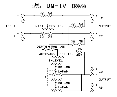
Autovary
When I read about the QS Variomatrix, I wondered if a passive speaker matrix could have separation enhancement. Then I got a copy of an electronics projects book with a tubeless squelch circuit. 15 The circuit uses the fact that a light bulb increases its resistance tenfold when it is lit and hot. This proved useful.
I connected a light bulb into the Depth circuit of one of my UQ-1 decoders.
A 50 ohm rheostat and a switch to short both out were connected in parallel with the
light bulb. This adds what I call the Autovary blend to the back channels when a strong center
front signal is present.
My UQ-1A contains my back Autovary circuit. Follow the link to see it. By this time I designed UQ-1A, I discovered that the switch was unnecessary, since I was always setting the Autovary control to the same place whenever I turned it on.
The Autovary system seems ideal. I have never heard any pumping from it. Apparently the light bulb has just the right timing to make the change in matrix decoding angle inaudible. And it does not disrupt concert-hall ambience located at center back.
I also designed another Autovary circuit to automatically adjust front decoding angle. It did not work as well as the back one.
The third form of separation enhancement was automatic matrix varying. It works by quickly changing the matrix coefficients to maximize separation between the signals that are actually there.
This separation-enhancement system preserves the fainter sounds, including concert-hall ambience.
The matrix varying does nothing to fix the side localization problem.
The Surround Master system uses this method.
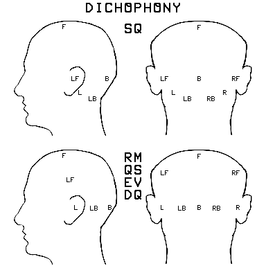
Ordinary stereo headphones can be used to decode SQ and RM recordings without the usual decoder:
Benjamin B. Bauer (CBS labs) discovered that ordinary stereo headphones can be used to decode SQ matrixed recordings. 17
This SQ decoding takes place in the human auditory system.
- The sound images are inside the head.
- Their locations are shown in the top set of diagrams at right.
While experimenting with SQ Dichophony, I discovered a similar pattern that works for RM and QM recordings.
This decoding also takes place in the human auditory system.
- It works for Sansui QS, Electro-Voice Stereo-4, Dynaco diamond, and Dynaquad
Surround recordings.
- The sound images are inside the head.
- Their locations are shown in the second set of diagrams at right.
This decoding also works for Dolby Surround and Surrfield recordings (below).
- In these cases, the sound images seem to be outside the head near the
locations in the second set of diagrams.
- In the case of Surrfield, the images seem to be at the original distances of
the sounds.
This makes dichophony sort of a universal decoder for SQ, and RM/QM. It does not work correctly for UMX/BMX or Matrix H (below). It might work with Ambisonics UHJ.
I use this trick to monitor live RM mixes when I am mixing a stage performance with no control room or no quadraphonic speakers. It takes some practice to hear it correctly, but I usually get the mix I want.
In 1974, the British Broadcasting System ran a series of trials 20 between eight different matrix systems:
- Matrix A was QS, no logic.
- Matrix B was SQ, no logic.
- Matrix C was QS, with Variomatrix.
- Matrix D was SQ, with front-back logic.
-
Matrix E was a high separation tetrahedral matrix Peter Scheiber proposed (at right). 8
Matrix E (Scheiber)
Matrix H (BBC)
- Matrix F was BMX, no logic.
- Matrix G was BMX modified to reduce the phasiness in the stereo image.
- Matrix GX was Matrix G modified to further reduce the phasiness (short lived - not tested).
- Matrix HX was Matrix GX modified to further reduce the phasiness (short lived - not tested).
- Matrix H was Matrix HX modified to further reduce the phasiness.
- Matrix J was Matrix H modified to further reduce the front phasiness (done after the trials ended).
- Matrix HJ was Matrix J modified to further reduce the phasiness (done after the trials ended).
- Matrix UHJ Ambisonic (below) is Matrix HJ with the B format for the encoded signal.
The result of these trials was a choice for Matrix H, which was used for only a few experimental recordings, although after it was published, some other record companies tried it. Its stylus motion diagram is shown here at right.
In addition, one set of published specifications accidentally showed playback parameters instead of recording parameters. A few recordings were made with the reversed parameters, reversing the directions of the stylus rotations. I call this version HR.
In 1977, separation enhancement similar to the QS Variomatrix was added to Matrix H for experiments. 21
The goal of Matrix H seems to be mono compatibility for sounds at center back. Only BMX/UMX, Matrix G, and Matrix H encode sounds panned to center back in a way that they play through a mono player. No other matrix (except the then future UHJ Ambisonics and my surround-field system) could do this.
All of the systems tested by the BBC have symmetrical separations between adjacent channels. But what they failed to do in these matrix trials was to test the front-oriented (QM) matrices Stereo-4 and Dynaquad. For concert-hall ambience recovery, these perform much better than any of the systems the BBC tested.
I didn't have access to the article above until 2006, because I did not know what to search for. I found it by accident while searching for something else.
In 1975, the rock band "The Who" made a movie version of their rock opera "Tommy". The title of the movie was "Tommy - the Movie". It was the first movie made in matrix surround sound. 0
Their system, called Quintaphonic Sound, used a then-standard three-track film soundtrack. But they encoded the left and right track in the Sansui QS matrix. The center track was a third discrete track used for the movie dialog. The Sansui QS logo and the words "Quintaphonic Sound" are included in the opening title and end credits.
The problem was that most of the theaters showing the movie did not have a QS decoder, and just played the three-track soundtrack through the three speakers behind the screen. But even then, the out-of-phase nature of the back information caused people sitting near the front of the theater (facing forward) to hear the surround effects anyway.
When stereo VHS copies of this movie were made, the Quintaphonic sound was retained, with the dialog track mixed equally into the left and the right track, to produce a normal QS recording.
The soundtrack album is an enigma. There appear to be two versions of it.
- The first version has the QS encoding from the movie.
- Polydor was the record company that sold the album. When Polydor signed contracts for the CD-4 system (instead of QS), they apparently created a new mixdown of the album that removed the QS encoding.
Dolby Laboratories originally created Dolby Stereo for the movie "Star Wars". The basic matrix used is a combination of the Hafler diamond and QS. 0 But they made some changes to the basic matrix that made Dolby Stereo much more successful than any previous quadraphonic system:
- The 4 channels are Left, Right, Center, and Surround.
- These 4 channels are encoded onto a stereo soundtrack as the Hafler diamond was encoded, except that the surround channel is shifted by 90 degrees first.
- The Left, Center, and Right speakers are placed behind or over the screen.
- Multiple Surround speakers are placed on both sides of the audience. Multiple speakers are used to keep the human hearing system from locating any one surround speaker, and to make the effects work no matter where the listener is located in the theater.
- When the soundtrack is being made in the studio, the following events happen to the sound:
- The Surround channel is filtered to roll off the treble above 7 KHz.
- The Surround channel is Dolby B encoded.
- The matrix is encoded, producing the Left Total and Right Total signals.
- When the film is being played in the theater, the following events happen to the sound:
- The matrix is decoded, producing the Left, Center, Right, and Surround signals.
- The Surround channel is filtered to roll off the treble above 7 KHz.
- The Surround channel is Dolby B decoded.
- The surround channel is delayed by an amount adjustable from 5 ms to 30 ms. The delay is adjusted for the size of the theater.
- These processes combine to produce the following effects:
- The Surround channel filtering keeps sounds in the surround channel from being heard up front.
- The Dolby B noise reduction further separates the Surround channel from the others.
- The Surround channel is given more separation from the other channels than it would otherwise have.
- The delay keeps the listener from hearing screen dialog from the surround speakers.
- As long as the listener faces forward, the combination of the three speakers behind the screen and the multiple surround speakers solves the problem of hearing sounds in all directions. The sound can be panned according to the Hafler and QS rules and the listener will hear the sound in the correct location with no ambiguity.
Thus, the delay solves the problem of correct side image location.
Dolby Stereo
Dolby Surround
Stylus motions
Later, Pro Logic was added to Dolby Stereo to increase the separation. It works very much like the QS Variomatrix works.
In the early 1980s, the surround sound of Dolby Stereo was made available to the general public with the production of Dolby Surround VHS tapes and home components. They are designed to work in the home (with fewer surround speakers and fewer adjustments). A decorrelator is added to the surround outputs to keep the listener from locating the surround speakers.
From 1977 to 1980, I kept buying movie soundtrack albums and finding that they decoded perfectly in QS. For those 4 years, I thought they were encoding the movies in QS. The only movie surround system I knew about was the QS system used for "Tommy".
I had no information on Dolby Stereo, because the audio magazines I subscribed to did not cover movie theater sound. So I thought (from the name) that Dolby Stereo was just a noise-reduction system (I saw it in the movie credits). In 1980, Peter Scheiber told me about Dolby Stereo being a surround sound system. I then found some articles about Dolby Stereo and the home version called Dolby Surround. 0
Dolby Surround works with records, tapes, FM radio, CDs, and VHS as well as with film soundtracks. It works quite well for concert hall ambience too. Some CDs were made in Dolby Surround for just this purpose. For quadraphonic purposes, Dolby Surround blew everything else out of the water (including CD-4).
Dolby Surround fixes the side imaging problem. When the listener is facing forward, all of the sounds come from the correct direction. And it works quite well no matter where the listener is sitting in the theater.
Dolby Surround fixes the panning problem. When the listener is facing forward, all of the sounds come from the correct direction and move in the expected directions when standard panning techniques are used. This also works quite well no matter where the listener is sitting in the theater.
A Dolby Surround decoder can be used to play any RM or QM matrix, including QS, Stereo-4, Dynaquad, and others. Even though the speakers are not located where these matrix systems expect them to be, the sound images are very close to where these systems intend them to be. And the side images work.
The converse is true too: An RM or QM decoder can correctly play a Dolby Surround recording. This is why I thought those soundtrack records were in QS. The side imaging is only partially fixed in this case.
A few experimental movies were made IN 1978 with a 3-D version of Dolby Stereo that had high and low speakers in the theater. The height was encoded with the clockwise and anticlockwise motions common to SQ. The encoding of these movies also made it to the soundtrack albums.
In the Dolby Surround diagram above, the black circle (clockwise) is the down direction. The brown circle (anticlockwise) is the up direction.
I seem to have two of these records - at least, they seem to have the encoding. And they were made too early for them to be encoded in Circlesurround:
- The Wiz (1978). This was advertised as having height encoding.
- Thank God it's Friday (1978)
I decoded this with my passive decoder (below), set to the UQ matrix. I also set the Left Back speaker on the floor at center back, put a milk crate on top of it, and put the Right Back speaker on top of that. All of the speakers were originally sitting on milk crates to raise them off the floor (so the image speakers mentioned above could be put under the milk crates). This gave me the 3-D effect when I sat in the center.
Dolby Surround uses delayed back channels. Delaying the back channels provides the delayed sound cues that provide the correct image location for sounds panned in any direction from the listener. When the listener is facing forward, all of the sounds come from the correct direction.
The fourth form of separation enhancement was delayed back channels. Delaying the back channels provides the delayed sound cues that provide the correct image location for sounds panned in any direction from the listener.
This is the first system that provides panning the sound in any direction and having the listener hear it in the proper direction. But it has one problem: The listener must be facing forward. But it does fix the side-localization problem.
In 1978, I took an applied linear algebra course. I learned how to use the mathematical entity called a matrix. The matrix quadraphonic systems are based on this mathematical kind of matrix. Here are the rules of matrix.
The following equations are the matrix equations used in quadraphonics:
- F ... Original 4 Channels to Encode
- E ... Encoder Matrix
- C ... Encoded Program for Record or Tape
- D ... Decoder Matrix
- S ... Decoded Output to Speakers
- C = E F ... Encoding Equation
- S = D C ... Decoding Equation
- S = D E ... Combined Encode-Decode Effects Matrix
- S = D (E F) ... Entire Encode-Decode Process
The process used for quadraphonic matrix is called matrix multiplication.
The Electro-Voice Stereo-4 System is shown. But it works for any matrix system.
| ENCODER | DECODER | ||||||||||||||||||||||||||||||||||||||||||||||||||||||||||||||||||||||||||||||||||||||||||||||||||||||||||||||||||||||||||||||||||||||||||||||||||||||||||||||||
|
|
||||||||||||||||||||||||||||||||||||||||||||||||||||||||||||||||||||||||||||||||||||||||||||||||||||||||||||||||||||||||||||||||||||||||||||||||||||||||||||||||
| COMBINED | |||||||||||||||||||||||||||||||||||||||||||||||||||||||||||||||||||||||||||||||||||||||||||||||||||||||||||||||||||||||||||||||||||||||||||||||||||||||||||||||||
|
|||||||||||||||||||||||||||||||||||||||||||||||||||||||||||||||||||||||||||||||||||||||||||||||||||||||||||||||||||||||||||||||||||||||||||||||||||||||||||||||||
The ironic thing is that matrix mathematics is often taught in a course which is often called "Discrete Mathematics".
Dolby Surround quickly became the de-facto standard for surround sound recording from around 1978 to the late 1990s, when Dolby Digital started to appear in DVDs. Most VHS tapes are in Dolby Surround, as is the analog track of most DVDs.
Even phonograph records, cassette tapes, and CDs were recorded in Dolby Surround, and most CDs of film soundtracks still are (as of 2019). Discrete systems need up to 7 channels to equal it in sound location.
Dolby Surround is a versatile and useful surround sound system that should have remained the standard. It is still quite useful. I have encoded live recordings in it. Unfortunately, the upgraders always want to change things.
The two main separations perceived by listeners are:
- separation between front and back
- separation between left and right front
The two systems that take advantage of the main separations are:
- The Hafler-Dynaco Diamond
- Dolby Surround
In both cases, the speaker locations coincide with the main noticeable separations. This reinforces these separations.
Fortunately, Dolby Surround is still available to most people.
Tristereo Bone Fone
I bought a Bone Fone in 1980 in a used goods store. This is a headphone-style device that is worn over the shoulders. The idea is to improve bass response through bone conduction. I got the one that was just a headphone, not the one with a radio in it. It worked well as it was, but I decided to improve it by adding surround sound to it.
 I took the cloth cover off of it and noted how the speakers were mounted. Then I
mounted an identical speaker in the back of the neck. Using the design of my Tristereo
(right), I wired one terminal of the new speaker to the hot terminal of the left speaker and
the other terminal to the hot terminal of the right speaker. Then I put the cover back on.
I took the cloth cover off of it and noted how the speakers were mounted. Then I
mounted an identical speaker in the back of the neck. Using the design of my Tristereo
(right), I wired one terminal of the new speaker to the hot terminal of the left speaker and
the other terminal to the hot terminal of the right speaker. Then I put the cover back on.
This will decode all of the RM and QM matrix systems, as well as Dolby Surround.
(The photo is from an old ad for this device.)
Compatiquad
Before the details of the EV universal decoder were published, I devised a decoder that could play QS, Stereo-4, Dynaquad, Hafler diamond, and SQ records when they are stacked together on a record changer. It does not require adjustment during the stack.
The decoding coefficients were chosen for the following purposes:
- Optimum performance with concert-hall ambience.
- Almost perfect decoding of all Regular Matrix discs (which are all very similar).
- Playback of SQ records with the object of maximizing front-to-back separation, rather
than the side-to-side separation CBS wanted. This was done for two reasons:
- I earlier showed the lack of a need for much separation between the back channels.
- Classical music and ambience benefit much more from front-to-back separation.
In 1976, I had an idea for making a passive matrix decoder that goes after the power amplifiers and can decode all matrix systems. I then built a small version that could do just RM, QM, and CQ, and the CQ part worked correctly at only the midrange frequencies (the CQ decoder above). I called it UQ-4.
In 1981, I built the entire device. This works at all audible frequencies and handles more matrix systems. I called the finished unit UQ-44.
How I Afforded this Project
I was an independent contractor repairing record changers at the time most of the quadraphonic developments happened. This did not pay enough for the experiments I wanted to do. I also did some tutoring for university students. But I had some very good luck.
Once a year, the local university had a surplus materials auction, and I went to it to get some bargains I could otherwise have never been able to afford, including some large wooden office desks at $2 each, floor lamps at $1 each, and several shelf units. My secret was to bid first with a very low bid, and not to raise it. They usually had several lots of each item in the auction, and I often got the second or third lot because nobody else bid.
I also bought electronic parts and equipment. My best scores were a teletype machine for $1 in 1981 (my first computer printer), a Dynaco PAT-4 preamp for $10 in 1976, and for $1 in 1980, a group of 10 large cardboard boxes full of unused transformers, capacitors, resistors, rheostats, coils, switches, and many other electronic parts. Nobody else bid on any of these except the preamp. Included in the boxes of parts were most of the parts used in this project.
The key parts I needed that were in those boxes were a pair of high power audio output transformers that each had two 8-ohm output windings. They had a high winding count and low DC resistance that made them stable for the purpose I used them for.
The two transformers mentioned in the box on the right were the key to the design. On each transformer, I connected the two 8-ohm windings together to produce a phase inverter. To keep the primary winding from developing high voltages, I put a load resistor on each one. These were the central components of my design.
Using coils and capacitors, I turned each transformer into two ψ (psi, or frequency-dependent) phasor units spaced 90 degrees apart. I fed one from the left channel input and one from the right channel input. I used L-C circuits, rather than the R-C circuits in most phasor circuits, because the outputs had to drive low-impedance speakers.
I used rotary switches and the basic circuits of the UQ-1 decoder (with some preset rheostats) to complete the decoder. It decodes the following matrix systems:
- QS
- Dynaquad
- Stereo 4
- Compatiquad (CQ - see above)
- SQ
- EV Universal
- UQ Equal Separation
Four more rotary switch positions provide the following variable matrix settings. The Width and Depth controls from the UQ-1 design allow adjusting each matrix:
- Variable Basic Matrix
- Variable RM
- Variable CQ
- Variable SQ
In addition, I added a switch to let me decode BMX. It trades the left front and left back outputs. Using the Variable SQ position with full Width and no Depth provides the signals. The listener faces the left front speaker instead of the front. I did not yet have the details of Matrix H or UHJ at the time I built this.
I also built in a few accessories because I had the parts:
- Phase Reverse of left back speaker (known difference between some systems)
- Front and Back Autovary (see above)
- Front Phased Crossblend (to partly get rid of side imaging problem)
- Back Filter (later found out it was exactly what was needed for Dolby Surround)
- Bass Booster (fed some front bass to back channels)
- Speaker Orientation Rotation (like on Sansui QS-1)
- Discrete Input
- Headphone outputs with Fixler Matrix and Bauer 16 Headphone Circuits
- Oscilloscope output for 4-channel display
The UQ-44 is a cube about 1 foot on a side and weighs almost 20 pounds. The transformers were the size-determining factor.
The Problem:
After I got this working, I looked up how much it would cost to build another one. The results were shocking:
- Many parts in the phasor units (especially coils) were unavailable unless a production run of at least 4000 of each kind is ordered.
- Assuming I could buy coils at the equivalent wholesale unit price, all of the parts in one UQ-44 cost over $1000 (new parts, 1981 dollars).
- Removing the items listed in the accessories (except the phase switch) lowered the price to about $600.
- Removing the preset rheostats and adjusting Width and Depth controls for each matrix reduced the cost to about $450.
- The transformers alone were $100 each. This set a floor for the cost.
- None of these prices included the case or the labor to put it together.
I then figured that nobody would want to buy one. It was cheaper to buy a second amp than to buy this. But I enjoyed mine from 1981 until 1993 when I moved. I added Dolby Surround run through the discrete inputs, but used UQ-44 for older matrix records.
To contrast this, I built the first UQ-1 for less than $20 (1973 dollars).
The details of the UQ-44 are on this page: UniQuad UQ-44
I built three different headphone adaptors for quadraphonics:
- The one in UQ-44, which used 4 decoded channels to form a 2-channel signal for headphones using the Bauer 16 and Fixler 19 circuits. It could operate normal headphones or the 4-driver ones.
- In 1982, I built an inline adaptor for a 2-channel headphone output that used parts of the Bauer 16 circuit. It has an RM/SQ switch to select either the Bauer circuit (RM) or a circuit for SQ Dichophony 17 .
- In 1998, I modified a set of headphones to include a phase reverse switch for one earpiece. It aids in the mixing of RM and QM recordings without monitor speakers during a live recording. I recently made a second similar set.
I didn't have access to the Bauer articles until 1980.
I made some strange discoveries while listening to stereo records on the UQ-44:
- My stereo 'Herb Alpert and the Tijuana Brass' albums appeared to somehow contain back channel sound in SQ. I later decided it was more like BMX, because the lead trumpet was in the left back in SQ.
- Most of my 'ABBA' records showed the same effect. And again the lead vocal was in the left back.
- My RCA 'Vangelis' albums also showed this effect, but in this case, the lead sounds were up front in SQ, while accompaniment parts were in the back.
In many of these cases, the records were made before records made in those quadraphonic systems mentioned were released to the public.
What was going on? I did some investigating, and learned the following:
- The 'Herb Alpert' albums were recorded using the Haeco CSG (Compatible Stereo Generator - also known as the Holzer system - and as a process used by Jerry Moss of A&M Records). It uses 90-degree phase shifts to remove the oversize solo problem from stereo recording. Thus we have some records sounding like SQ or BMX, but made before these systems were invented. 0
- There are conflicting stories about the 'ABBA' records. One story was that the engineer got his hands on a Matrix H encoder. Other stories suggest BMX, the Stereo-180 microphone, and accidental phase shifts. But it is also known that WEA (Warner/Elektra/Atlantic - the record company 'ABBA' is on in the US) was using the Haeco CSG. 0
- 'Vangelis' recorded his material in SQ, but RCA wouldn't release an SQ recording because RCA was pushing CD-4. But RCA could not remove the SQ from the master recording, so they had to leave it. 0
Even before Dolby Surround appeared, many manufacturers discontinued quadraphonic products because they were not selling. There were several reasons:
- The economy was in a recession, and people were not buying more expensive records and equipment. Most record companies charged a dollar more (about 20%) for quadraphonic records.
- In 1975, many record companies stopped recording in quadraphonics because the records weren't selling. Too many people thought you had to have a quadraphonic system to play the records. But the only quadraphonic products that would not work with a stereo player were the discrete quadraphonic tapes and CD-4.
- Record stores were putting quadraphonic releases in a special "quadraphonic" bin in the special products part of the store, instead of putting them with the other records that artist recorded. This caused record companies to stop labeling the quadraphonic records as quadraphonic.
- Many record companies and stereo manufacturers did not want to produce quadraphonic products because there was no standard. Unlike the greed for royalties in the quadraphonic market, the Westrex 45/45 easily became a standard because the concept was patented by Alan Blumlein in 1933, and the patents had already expired (because nobody saw any commercial value to it until there was interest in stereo in the 1950s).
The marketing "experts" totally misread the market for quadraphonics. Sales of discrete 4-channel reel-to-reel tape recorders exceeded all expectations. But when other quadraphonic products appeared on the market, they didn't meet sales expectations.
It turned out that most of the 4-channel reel recorders were not going into home quadraphonic music systems. Musicians were buying them to create homebrew multitrack recording studios. Of all the manufacturers, only TASCAM figured it out.
The only discrete 4-track recorder I own is used for recording studio purposes. It has never been used for discrete quadraphonic playback, although it was used extensively to record and encode matrix surround sound.
Once Dolby Surround showed performance that none of the quadraphonic systems could match, most record companies stopped recording quadraphonic records:
- When Dolby Surround showed superior performance, record companies discarded the older quadraphonic systems they were using. This was a mistake in the case of QS, because Dolby Surround decodes QS perfectly.
- The last two companies to remove quadraphonic records from their catalogs were the classical music labels Angel (using SQ) and Vox (using QS). 0
- Some recording companies have been making classical CD albums in Dolby Surround.
Thinking about this shows that quadraphonic sound continued as Dolby Surround. It did not die.
Even though quadraphonic was "dead" in the markets, many die-hards kept it alive:
- One company kept selling quadraphonic recordings of passing trains for years - in CD-4.
I probably would have bought some of these records if they had been recorded in matrix instead of CD-4.
- Many records are covertly recorded in either quadraphonic sound (usually QS) or Dolby
Surround. These include:
- Many new CD releases of old matrix quadraphonic records still have the encoding.
- Many movies are in Dolby Surround or some form of Dolby Digital. VHS must use Dolby surround, but DVD and BluRay usually have both.
- Many movie albums are in Dolby Surround because the audio comes from the film. This is not usually mentioned.
- Engineers recording classical music use extra microphones to capture the concert-hall ambience. This is usually recorded out of phase in the recording, producing a Dynaquad recording.
- Some engineers know that many recordings will be played through a Dolby Surround system, and provided a recording with suitable content.
- Many recording engineers like the sound of QS when it is played in stereo, with the reverb and harmony parts spread wide.
- Note that the CD has no standardized playback equipment for discrete surround sound available to the public. So any desired surround sound must be recorded with a matrix system (usually Dolby Surround).
- Many recordings have been made in surround sound, but are totally unlabeled.
- A few recordings are being released in 5.1 digital and discrete quadraphonic using esoteric technologies such as SACD, DVD-A and other variants. All of them require expensive equipment and are incompatible with each other.
- A new surround sound system called Dolby Atmos has sounds at different heights. It is quite expensive.
- A new recording made in QS was released in 2018. It costs over $200, but comes with a working QS Variomatrix decoder on a PC board.
The problem with many innovations is that there is no standard. Every company hopes that its own patented development will bring it royalties, and every company wants to avoid paying royalties to competing companies. We have seen the same kind of market battles dividing various industries over and over again. Here is a list of battles over the years:
- The battle between AC power and DC power: This was short-lived in most locations because AC was cheaper to make and distribute. But it continued for years in New York City, where Consolidated Edison continued to supply DC. 0
- The battle between laterally recorded sound on records (the direction the stylus vibrates) and vertically recording records: Note that, as soon as all of the patents expired, all record companies switched to lateral records. 0
- The companies could not even agree on what speed records should rotate at, with speeds ranging from 70 RPM to 120 RPM (80 RPM being the norm). The National Association of Broadcasters (NAB) finally forced a standard speed of 78.26 RPM in 1928. They declared that all electric radio station turntables would turn at that speed, an average of Columbia (80 RPM) and Victor (76.59 RPM) speeds. They also declared that most radio station turntables would play only lateral records. 0
- Disagreement over the recording equalization for records: At least 20 different curves were used. Trying for a standard, the NAB and the Audio Engineering Society (AES) proposed very different curves, furthering the disagreement. The Recording Industry Association of America (RIAA) produced a compromise curve that ultimately became the standard for microgroove records. It became the standard in the US in 1957, and in Europe in 1962. Before that, people needed record players with switchable equalization. 0
- Columbia and RCA had a battle over whether microgroove records should turn at 33.33 RPM
or 45.00 RPM (the famous "Battle of the Speeds"). For a while, RCA did the same
thing they did with 78 RPM records, releasing classical music on 45 RPM records (with the
same annoying side breaks 78s had). This was one of the few cases where each company adopted
the other's technology by trading patent rights. The 45 was used for singles, while the 33
was used for albums and classical works. But if it hadn't been for the proliferation of
45 RPM jukeboxes, we might have had a standard speed of 33 and a standard hole size.
0
I do wish they had agreed on the size of the center hole. It would have made using my record changer that can change mixed speeds easier.
- A battle emerged between CBS, NBC (RCA & Westinghouse), and CTI (Color Television Inc.) over how color TV should be broadcast. CBS used a spinning color wheel in front of the camera and in front of the picture tube. It didn't work very well and was not compatible with existing black and white TV, but the FCC approved it in 1951. This was later revoked due to Korean War production restrictions, letting RCA show its fully compatible (with existing black and white TV) system that doesn't use more bandwidth. It was adopted in 1953, and, while still in use, it was replaced by incompatible digital TV for many countries in 2007. 0
- Several different open reel tape track formats competed for standardization. Two systems that were incompatible with each other were finally chosen for mono voice and stereo music formats. 0
- Several different broadcast video tape formats competed for standardization. The spinning head system won over the high speed linear system. 0
-
Several different methods for making stereo records were proposed. These battled from about 1952 until 1957. Among them were the Minter (Components Corporation) FM carrier in the groove system (see above), the Cook dual groove band system (two arms or a forked arm), the RCA side-by-side dual groove system (two styli), The Blumlein groove on each side of the record system, the Blumlein vertical-lateral system, and the Westrex 45/45 system. The Westrex system was superior, but it was adopted in 1957 only because Blumlein's already expired 1933 patents had priority, so no royalties would be paid by anyone to make 45/45 records in stereo. 0
Cook dual-groove
- Several different methods for broadcasting FM in stereo were proposed:
- The Crosley system (38 KHz FM subcarrier)
- The Minter system (played the Minter records over the air - 30Khz FM subcarrier)
- The GE-Zenith system (AM 38Khz subcarrier - SCA unchanged)
- The Fisher system (40 KHz FM subcarrier)
- The Geluk system (25 KHz pan control system - SCA unchanged)
- Three different car cartridge tape players battled for the market in the 1960s. The winner was the Lear Jet 8-track tape format. 0 Then the cassette completely replaced it.
- The quadraphonic record format battle this page is about.
- Four different video cassette formats battled for market supremacy, with VHS the winner. 0
- A similar quadraphonic FM broadcast format battle started:
- The Dorren system (38 KHz AM and quadrature and 76 KHz AM subcarriers)
- The Motorola system (38 KHz AM and quadrature and 76 KHz AM subcarriers - different modulations)
- The GE system (38 KHz AM and quadrature AM and 76 KHz LSB subcarriers)
- The Zenith system (38 KHz AM and quadrature and 76 KHz USB subcarriers - SCA unchanged)
- The RCA system (38 KHz AM and quadrature - no 76 KHz subcarrier- 3 channel - SCA unchanged)
- The Radio Programming Management system (three phase 38 KHz AM subcarrier - SCA unchanged)
- The Geluk system (25 KHz pan control system - SCA unchanged)
- The CBS proposal - Use matrix quadraphonics - no discrete broadcasting - SCA unchanged)
The FCC initially decided that matrix was good enough, and didn't approve any discrete system (They made this decision when Dolby Surround was the system in use by almost everyone).
They later approved the Dorren system with no SCA, but nobody ever used it. 0 - The battle over different AM stereo systems: No system was ever chosen. 5 different systems were allowed to coexist, with the radio station choosing which to use. 0
- Many market battles have occurred since the 1970s, including the various formats for digital recording, digital TV, and computer data storage. All of these battles are detrimental to consumers. We could have had compatible high definition television if Microsoft had not used its clout to force its incompatible formats upon us. 0
It is time to remove the power of patents and copyrights that keep the best systems from being adopted and cause the removal of old systems from the market. Their periods should be shortened, the royalties should be reduced to amounts equivalent to the mechanical royalty, and licensing must be compulsory.
UHJ Ambisonics
Michael Gerzon 22 and others started developing Ambisonics in 1974. It is yet another matrix system that can have additional transmission channels added to increase separation.
This is derived from the BBC Matrix H. It is designed to further remove the phasiness heard during normal stereo playback of the recording. It also has mono playback compatibility, with no sounds encoded as vertical stylus motions.
There are 4 versions of UHJ:
UHJ 2 - A 2-channel version that can be put on records, tapes, and CDs.
UHJ 2.5 - A 2-channel version with an ultrasonic enhancing signal.
UHJ 3 - A 3-channel system for multichannel media.
UHJ 4 - a 4-channel system for multichannel media with height.
A small group has continued to make recordings in Ambisonics, and equipment is still available to play it. Some recordings are released as ordinary CDs. And virtual reality uses it.
This can be played on a normal stereo, or with an SQ decoder with both back speakers connected to the right back output. A Dolby Surround, RM, or QM decoder will also work, but not as well. This is a good design for adding mono compatibility that is hampered by lack of available equipment.
I didn't have access to the article above until 2006.
Circlesurround
Sound Retrieval System (SRS) owns Circlesurround, which was introduced in the mid 1990s. It was introduced to provide a matrix method of having two different surround speaker signals for Dolby Surround in theaters, and on VHS and DVD. Movies have been encoded in Circlesurround; Theaters have been equipped with circlesurround decoders; and many receivers and decoders have circlesurround capability. Dolby Surround decoders can also play Circlesurround, but without the separation between the surround speakers. 0
Circlesurround has also been sold for automotive surround sound. It does synthesize surround sound from ordinary stereo. It has a pleasing surround effect.
Circlesurround makes no sense to me, because the encoding holes at the left side and right side encode the sound closer to center front than the left front and right front signals are encoded. This system is nothing but SQ with the left and right back signals traded and moved forward. It is essentially the front half of SQ with the channels traded.
You can play Circlesurround with an SQ or EV Universal decoder by trading the left back and right back speakers. Dolby Surround also plays it adequately.
Surrfield
Stylus motions
Spheround
In 1996, I was recording a soloist rehearsing a speech. I was using some microphones on a 3-mic surround stand I had made a few weeks earlier. The speaker was about two feet from the L and R mics. The soloist practiced the part a few times before the first take. Then we recorded the take.
I rewound the tape to play it through the monitor speakers (in regular matrix), and started the tape playing at the beginning. Then the following conversation took place:
- Me: "Would you please stop practicing? I want to hear the tape."
- Soloist: "That's not me. It's the tape!"
It sounded so real that I didn't realize it was the tape playing. I thought it was the soloist practicing again.
After this, I continued to experiment and perfect the system over several years. In one of the experiments, I had someone walk around the mic cluster at different distances, speaking as he walked (he kept saying, "Can you hear me now?" in a gag reference to a cell phone ad). On playback, I could hear not only the direction but the approximate distance of his voice.
This system closely mimics both the shadowing effect of the head on the ear farthest from the sound (which a panpot does) and the delay of the sound from one ear to the other. These combine to produce a stable image no matter which direction the listener is facing. It also produces a correct image to the side of the listener with a quadraphonic (RM) speaker layout, again without regard to the direction the listener is facing.
This system works for both headphones and speakers.
Another effect this system produces is a steering effect that guides the ear to the correct direction. This happens because the mics farthest from the sound pick up the sound too, and the echoes from that sound, and present them delayed in the opposite speakers.
I have heard many different attempts at realistic sound, using speakers or with headphones. But this is the only one that has a "you are there" quality I have never heard elsewhere. I call the process "Surrfield".
The sound images are perfectly located without any separation enhancement, even when the individual instruments are panned to locations different from the general location of the entire band.
I devised a 3D version of this called Spheround. The stylus motions are at right.
Both of these fix the side localization problem no matter which way the listener faces.
See these pages for more on this process:
This entails was putting enhancement in the recording. There have been several different attempts to do this:
- My surround field recording system (above)
- Dolby Surround Soundbars - This system creates a surround effect through speakers in a soundbar. Note that with this system too, if you turn to look to the left or the right, the effect disappears.
These systems can fix the side localization problem.
The fifth form of separation enhancement was putting enhancement in the recording. There have been several different attempts to do this:
- Binaural - This was an attempt to use a dummy head with microphones in ears to record a realistic surround sound. It worked quite well if your head was the same size as the dummy head and your ears had the same shapes.
- Ambisonics - This attempts to create a stable image through phase changes and multiple speakers.
- Sound Retrieval System - This system creates a surround effect through stereo speakers. The devices have this logo "(•)" on them. But if you turn to look to the left or the right, the effect disappears.
- My surround field recording system (above)
- Dolby Surround Soundbars - This system creates a surround effect through speakers in a soundbar. Note that with this system too, if you turn to look to the left or the right, the effect disappears.
These systems can fix the side localization problem.
CD-4 died long before the phonograph record did, but something with the initials "CD" did kill off the phonograph record: The Compact Disc (CD).
I prefer the phonograph record over the CD.
Note that the matrix systems work just fine with CDs. I have several CDs that are marked QS, one that is marked SQ, several in unmarked SQ, and quite a few marked as being in Dolby Surround. In addition, many of the reissues on CD of records that were originally encoded in a matrix are also encoded on the CD. Many soundtrack albums are in Dolby Surround. And some record producers are also making CDs in Dolby Surround.
Some companies are still making records. I bought a new one in 2014, and several more in later years.
A new record made in QS was released in 2018. It comes with a working QS Variomatrix decoder on a PC board.
People who collect recordings are finding that there is a lack of working equipment for playing older recordings. In addition, many of the recordings themselves are deteriorating:
- Many electronic devices 15 years old or older have quit working. There are several things
that can go wrong with them:
- The electrolytic filter capacitors in the power supplies go bad. Many of them dry out and have no capacitance at all. Others "reform," increasing their capacitance while reducing the voltage they can stand. This usually happens if the equipment is not used for many years. When turned on after many years of disuse, the voltage from the power transformer might be too high for the capacitor. It shorts, and may explode. Sometimes this also burns out the power transformer.
- Tubes go bad. Except for a few types used in guitar amps, replacements have not been made for many years.
- Many devices used proprietary integrated circuits that are no longer available.
- Other parts (particularly potentiometers) are oxidized by the air and fail or become noisy.
- New reel-to-reel, cassette, and VCR players are rare, if they are sold at all.
- New reel-to-reel, cassette, and VCR tapes are no longer sold.
- The rubber belts and drive wheels in record players and tape recorders go bad. Often the parts are no longer available.
- Many of the better turntables have customized pickup cartridges that are not made anymore.
- Styli for many pickup cartridges are no longer made. Many pickup cartridge companies have gone out of business or have stopped making record playing equipment.
- Often the 78 RPM stylus is no longer made for the cartridge, even if the microgroove stylus is still available.
- Nobody makes the CD-4 pickups and styli anymore.
- The heads go bad in tape recorders and VCRs.
- The LASER heads in CD and DVD players go bad.
- The glue holding the oxide to recording tape dries up and the oxide falls off the tape.
- The glue holding the oxide to recording tape absorbs moisture and becomes sticky, causing a problem called "sticky-shed". This causes the oxide to stick to the tape heads, fouling them and keeping the tape from moving.
- New players no longer can play older formats. This was first seen when many turntables made in the 1970s no longer had the 78 RPM speed. One would wonder if the cheap 3-speed turntables sold today have the 78 RPM stylus as well as the 78 RPM speed.
- Nothing sold today can play the quadraphonic matrix systems (except that Dolby Surround systems can play the RM and QM formats).
- The special replacement stylus for playing CD-4 records is no longer made.
- The special turntable cables for playing CD-4 records are no longer made.
- Replacement IC chips for quadraphonic decoders are no longer made. Fortunately, the early decoders used common transistors that are still available.
- New home theater systems use digital connectors that are incompatible with quadraphonic equipment.
The problem is that all manufacturers make things that will sell in large quantities, not what people actually need.
With the advent of digital formats for video recording (DVD and Blu-Ray) came a caboodle of new discrete digital sound encoding techniques that are incompatible with each other. We lost the simplicity of one standard that Dolby Surround provided for more than 25 years.
Unless it is deliberately encoded into the discrete recording, we also lost the side image location fix that Dolby Surround provided.
There should be a law requiring any manufacturer producing a new product that changes or removes an existing standard to either keep making equipment for the old standard or to pay for conversions of all old software and recordings to the new standard, ensuring the compatibility of old recordings or software with the new standard.
One suggestion is a multichannel digital to matrix converter. Connect it to the discrete outputs of a DVD or Blu-Ray player and use it with your old receiver.
The compression methods used to shrink the music in a computer file for MP-3 also remove some information from the file. This often removes information from the recording, including precise pan position, surround encoding, and concert-hall ambience.
I took some of the matrix-encoded recordings I made and converted them to MP-3 format to enter them in an original recordings contest. A flute part I added to change the timbre of an organ part totally disappeared from the MP-3 version. The MP-3 encoder treated that entire flute part as harmonics of the organ part, and thus, MP-3 removed it as "unnecessary information". It also changed the panning of the reverb (panned into the surround speakers) into only the right channel, destroying the surround effect.
I built the UQ-SSC-10 ten-channel matrix switching system to be able to decode any of the matrix systems ever used. The details are here.
It is no longer in use.
With it, I discovered that the location of a sound becomes more distinct when more channels are used, even though they are just decoded at different directions in the same matrix.
With the decaphonic system, I finally got to try out the octophonic system I sketched out in 1970, but with adjustable matrix parameters. It would have produced better sound images than any quadraphonic system has made.
This system can play all of the following matrix systems:

UQ-SSC-10
- Scheiber
- Sansui QS
- Dynaco Diamond
- E-V Stereo 4
- Dynaquad
- CBS SQ
- CBS SQ 10-40 blend
- Denon UMX, BMX, and UD-4 (baseband)
- E-V Universal
- BBC Matrix H
- BBC Matrix H reversed
- UniQuad ES
- Dolby Surround
- CircleSurround
- BHJ Ambisonic
- Hexaphonic Tridee
- Tetraphonic 3D
- Compatiquad
- Phase Positioning
- Surrfield
- Spheround
This uses many channels with decoding coefficients close to each other. Some movie theater systems use multiple discrete channels, but it works just as well with matrix systems.
Provision of many channels keeps the ear from finding the speaker location instead of the sound location.
With the discrete systems, several speakers in different directions carry the information for the human ear to locate the sound. It also works, no matter which way the listener is facing.
With discrete systems, the sounds still "cog" between speakers, but the steps are smaller with more channels.
The production of a discrete recording must ensure that the correct information is in each channel of the recording so the sounds come from the correct direction. But a matrix decoder can automatically place the sounds in the correct places to make this work.
This idea seems counterintuitive, but it works. My page on Surround Fields shows how this works. The use of the surround field recording method makes it work even better, because the direction is encoded in the recording.
The direction the listener is facing does not matter and with the Surrfield, the sounds do not "cog" between the speakers.
An 8-channel version (UQ-8) appears on the page. It also covers the use of a 12-channel decoder.
These systems partially fix the side localization problem by increasing the number of cogging steps.

Dolby 7.1

UQ-8

UQ-12
The sixth form of separation enhancement was using many channels with decoding coefficients close to each other. Some of today's movie theater systems use multiple discrete channels to achieve this (Dolby 7.1, right), but it works just as well with matrix systems.
Provision of many channels keeps the ear from finding the speaker location instead of the sound location.
With the discrete systems, several speakers in different directions carry the information for the human ear to locate the sound. It also works, no matter which way the listener is facing.
With discrete systems, the sounds still "cog" between speakers, but the steps are smaller with more channels.
The production of a discrete recording must ensure that the correct information is in each channel of the recording so the sounds come from the correct direction. But a matrix decoder can automatically place the sounds in the correct places to make this work.
This idea seems counterintuitive, but it works. My page on Surround Fields shows how this works. The use of the surround field recording method makes it work even better, because the direction is encoded in the recording.
The direction the listener is facing does not matter and the sounds do not "cog" between the speakers.
An 8-channel version (UQ-8) appears on the page. It also covers the use of a 12-channel decoder.
This uses many speakers for each channel.
In this case, a small speaker is placed on each side of the main speaker for each channel and played at a lower level. These speakers form a rough dodecagon collapsed into a square. The main speaker is normally heard unless the sound source is between the speakers. Then the small speakers are found by the ears to be the sound source because their sounds add together.
Provision of many channels keeps the ear from finding the speaker location instead of the sound location.
This partially fixes the side localization problem with multiple targets.

Extra Speakers
This form of separation enhancement is using many speakers for each channel.
In this case, a small speaker is placed on each side of the main speaker for each channel and played at a lower level. These speakers form a rough dodecagon collapsed into a square. The main speaker is normally heard unless the sound source is between the speakers. Then the small speakers are found by the ears to be the sound source because their sounds add together.
The tiny bumps in the diagram are L-pads or 50Ω rheostats used to reduce the volume of the small speakers to the correct level.
Provision of many channels keeps the ear from finding the speaker location instead of the sound location.
Poincaré Sphere
With several different kinds of separation enhancement available if desired, just how much information is needed to place a sound source in any place in the room?
Using the old Dolby 3-D system or the Spheround system (both have identical direction coding), only 2 channels (e.g. a stereo record) are needed to encode the direction a sound comes from in any direction in a sphere surrounding the listener.
The Poincaré Sphere, representing phono stylus modulations, is shown in the diagrams at right and below.
The Poincaré Sphere is used as follows:
- All modulations are on the surface of the sphere.
- Horizontal stylus motion (mono) is at the right of the sphere (olive) and encodes sounds in front of the listener.
- Vertical stylus motion is at the left of the sphere (violet) and encodes sounds behind the listener.
- The left channel diagonal (cyan) is on the far side of the sphere and encodes sounds to the left of the listener.
- The right channel diagonal (red) is on the near side of the sphere and encodes sounds to the right of the listener.
- Clockwise stylus motion (black) is at the top of the sphere and encodes sounds below the listener (nadir channel).
- Anticlockwise stylus motion (brown) is at the bottom of the sphere and encodes sounds above the listener (zenith channel).
Sphere stylus vectors
Distance from the listener can be adjusted by how much reverb is on each channel. Farther objects are softer and have more reverb.
The basic 2-channel media can be used alone or with any appropriate separation enhancement. Examples:
- Use two Sansui Variomatrix systems, one set up for QS and one for SQ:
- Place the QS speakers in the 4 corners (LF RF LB RB).
- Place the front SQ speakers at straight left (LF) and straight right (RF).
- Place the back SQ speakers at straight down (LB) and straight up (RF).
- Use two Surround Master™ decoders in the same way.
- Use the 10 channel setup in Surrfield and Spheround in the same way.
More signal channels can be used to increase the separation between speakers, but a different encoding is needed.
This form of separation enhancement uses extra speakers for each channel.
In the first case, a small speaker is placed on the other side of the surround
area.
- The extra speaker is placed on the opposite side of the listener at a greater
distance from the listener than the primary speaker.
- It is played at a lower level.
- The speaker phase can be selected.
In the second case, an image projecting soundbar is used to focus the sound images.
- The soundbar is placed between the front speakers.
- This soundbar is played at a lower level.
This keeps the ear from finding the speaker location instead of the sound location.
This system fixes the side localization problem.
See my version below.

Case 1

Case 2

Case 3
Extra Speakers
This form of separation enhancement uses extra speakers for each channel.
In the first case, a small speaker is placed opposite to its primary speaker.
- The extra speaker is placed on the opposite side of the listener at a greater distance
from the listener than the primary speaker.
- It is played at a lower level.
- The two speakers are in phase.
In the second case, One small speaker is placed behind the adjacent speaker on
each side.
- This speaker is at a greater distance and played at a lower level.
- The two speakers are in phase.
In the third case, small speakers are placed near their main speaker.
- They are aimed into sound-conducting tubes to provide delayed sound at the adjacent
speakers.
- The speaker at the other end of the tube is aimed in the opposite direction.
- These sounds travel in opposite directions in the same tube.
- These speakers are in phase.
The delayed sound from the extra speaker reinforces the location of the main sound in the human hearing system.
The extra speakers do not have to be in exact positions, but need to be heard by the other ear.
This keeps the ear from finding the speaker location instead of the sound location.
See my version below.
I did the calculations for the new matrices and added them to the ones I knew about earlier, creating a new a table showing how well each system would work with various kinds of music. Systems no longer being considered in 1975 that were in the earlier list were removed:
| SYSTEMS WITHOUT SEPARATION ENHANCEMENT | ||||||||||||||
|---|---|---|---|---|---|---|---|---|---|---|---|---|---|---|
| System | Quadraphonic Separation | Stereo Synth Separation | Center Back − Mono ¤ |
Music Performance | Original Hole Locations |
|||||||||
| Front | Back | Sides | Front | Back | Mono- Back |
Hall Amb | Pop Mix |
Live Band | Stereo Synth | Mono play ¤ |
Side Image |
|||
| E-V Stereo-4 | 8.3 dB | 0.2 dB | 4.9 dB | 14 dB | 4.1 dB | 19 dB | 40 dB | Better | Good | Good | Better | Bad | Blur | Center Back |
| Dynaquad | 25 dB | 1.2 dB | 1.2 dB | 25 dB | 4.8 dB | 12 dB | 40 dB | Fair | Fair | Fair | Good | Bad | Blur | Center Back |
| Sansui QS | 3.0 dB | 3.0 dB | 3.0 dB | 8.3 dB | 8.3 dB | 8.3 dB | 40 dB | Fair | Good | Good | Good | Bad ◊ | Blur | Both Sides |
| CBS SQ | 25 dB | 25 dB | 3.0 dB | 25 dB | 3.0 dB | 3.0 dB | 40 dB | Bad | Good | Fair | Bad | Bad | Blur | Both Sides |
| CBS SQ Blend | 14 dB | 3.2 dB | 3.6 dB | 20 dB | 3.0 dB | 8.1 dB | 40 dB | Fair | Good | Fair | Fair | Bad | Blur | Both Sides |
| EV Universal | 8.3 dB | 3.0 dB | 5.2 dB | 14 dB | 3.0 dB | 8.3 dB | 40 dB | Good | Good | Good | Fair | Bad | Blur | Both Sides |
| UQ equal sep. | 4.8 dB | 4.8 dB | 4.8 dB | 11 dB | 3.0 dB | 6.8 dB | 40 dB | Good | Good | Good | Fair | Bad | Blur | Both Sides |
| Denon BMX | 3.0 dB | 3.0 dB | 3.0 dB | 8.3 dB | 8.3 dB | 3.0 dB | 3.0 dB | Poor | Good | Good | Awful | Best | Blur | Both Sides |
| Dolby Surround | 25 dB | 0.0 dB | 3.0 dB | 25 dB | 3.0 dB | 25 dB | 40 dB | Good | Good | Good | Good | Bad | Good | Both Sides |
| CircleSurround | 25 dB | 25 dB | 0.7 dB | 25 dB | 8.3 dB | 3.0 dB | 6.0 dB | Fair | Good | Good | Fair | Good | Fair | Both Sides |
| BBC Matrix H | 3.0 dB | 3.0 dB | 3.0 dB | 8.3 dB | 8.3 dB | 6.0 dB | 8.3 dB | Fair | Good | Good | Fair | Fair | Blur | Both Sides |
| Ambisonics UHJ | 12 dB | 3.0 dB | 3.3 dB | 12 dB | 3.3 dB | 3.6 dB | 5.4 dB | Fair | Good | Good | Good | Good | Fair | Both Sides |
| Surrfield on QS | 3.0 dB | 3.0 dB | 3.0 dB | 8.3 dB | 8.3 dB | 8.3 dB | ~5 dB | Fair | Good | Good | Good | Good § | Best | Both Sides |
| SYSTEMS WITH SEPARATION ENHANCEMENT | ||||||||||||||
| System | Quadraphonic Separation | Stereo Synth Separation | Center Back − Mono ¤ |
Music Performance | Original Hole Locations |
|||||||||
| Front | Back | Sides | Front | Back | Mono- Back |
Hall Amb | Pop Mix |
Live Band | Stereo Synth | Mono play ¤ |
Side Image |
|||
| QS Variomatrix | 15 dB | 15 dB | 15 dB | 15 dB | 15 dB | 20 dB | 40 dB | Better | Best | Better | Good | Bad | Blur | Both Sides |
| CBS SQ F-B Logic | 25 dB | 25 dB | 15.0 dB | 20 dB | 3.0 dB | 15 dB | 40 dB | Awful | Good | Fair | Awful | Bad | Blur | Both Sides |
| CBS SQ Variblend | 20 dB | 15 dB | 15 dB | 20 dB | 8.0 dB | 15 dB | 40 dB | Good | Good | Good | Poor | Bad | Blur | Both Sides |
| EV Universal Logic | 8.3 dB | 4.7 dB | 4.9 dB | 14 dB | 4.1 dB | 19 dB | 40 dB | Good | Good | Good | Good | Bad | Blur | Both Sides |
| UQ Autovary | 10 dB | 10 dB | 5.3 dB | 11 dB | 3.0 dB | 12 dB | 40 dB | Good | Good | Good | Good | Bad | Blur | Both Sides |
| Denon UD-4 | 20 dB* | 20 dB* | 20 dB* | 8.3 dB** | 8.3 dB** | 3.0 dB** | 3.0 dB | Better* | Better* | Better* | Awful | Best | Blur | Both Sides |
| JVC CD-4 | 20 dB† | 20 dB† | 20 dB† | ‡ | ‡ | ‡ | 0.0 dB | Good | Better† | Better† | None | ‡ | Blur | None ‡ |
| Dolby Pro Logic | 25 dB | 0.0 dB | 20 dB | 25 dB | 8.0 dB | 25 dB | 40 dB | Better | Better | Better | Good | Bad | Good | Both Sides |
| CS Logic | 25 dB | 25 dB | 10 dB | 25 dB | 15 dB | 15 dB | 6.0 dB | Better | Better | Better | Good | Good | Fair | Both Sides |
| Dolby Digital | 25 dB | 25 dB | 25 dB | ‡ | ‡ | ‡ | 0.0 dB | Better | Better | Better | None | ‡ | ≈ | None ‡ |
* Separations are at 3 KHz and below. Separations above 3 KHz are as in BMX.
** UD-4 uses BMX values for synthesis from stereo.
† Depends on the condition of the carrier.
‡ Not a matrix system. Does not synthesize from stereo, have a hole, or
lose sound in mono.
◊ This system provides best mono play by equally mixing decoder outputs.
¤ This is how each system plays on a normal mono player.
§ Front mics get delayed version of back sounds.
≈ Varies with how the recording was made.
~ Varies with how much of the back sounds get into the front mics.
In the separation table above, the "Center Back − Mono" entry shows how much of the center back signal gets to mono playback.
Most of the systems described above still have the same problem when the record is played through a monophonic radio or record player. When correctly encoded (as opposed to an error in encoding caused by an encoding hole) any sound panned to center back disappears from mono playback.
The stylus vector diagrams of most of the systems discussed so far still show a vertical line for the violet vector for center back. That means that it will disappear (except some crosstalk or distortion) from mono play.
Again note that in some of the diagrams, the blue vector and the magenta vector follow the same path (but with opposite rotation), and they seem to combine to produce a violet trace on a low-resolution monitor. Again, right-click on an image and click "view image" to display a larger version to see the two colors. Ignore such color combinations here.
Only UMX/BMX, Matrix G, Matrix H, and UHJ have center back signals that do not disappear in mono play. These are the mono compatibilities mentioned above. And in Spheround, the image steering signals of a center-back sound do not disappear.
Adding the new systems to the table of separations critical to the quality of concert hall ambience:
| SYSTEMS WITHOUT SEPARATION ENHANCEMENT | |||||||||||||||
|---|---|---|---|---|---|---|---|---|---|---|---|---|---|---|---|
| System | Separations to LB | Separations to CB | .. | Ambience Worst Case | |||||||||||
| Pan LF | 22.5° L | Pan CF | 22.5° R | Pan RF | Pan LF | 22.5° L | Pan CF | 22.5° R | Pan RF | Wd LB | Wd CB | Nr LB | Nr CB | ||
| E-V Stereo-4 | 4.9 dB | 10.1 dB | 19.0 dB | 11.2 dB | 5.3 dB | 5.1 dB | 10.7 dB | 40.0 dB | 10.7 dB | 5.1 dB | 4.9 dB | 5.1 dB | 10.1 dB | 10.7 dB | |
| Dynaquad | 1.2 dB | 4.3 dB | 11.7 dB | 17.7 dB | 6.0 dB | 3.0 dB | 8.3 dB | 40.0 dB | 8.3 dB | 3.0 dB | 1.2 dB | 3.0 dB | 4.3 dB | 8.3 dB | |
| Sansui QS | 3.0 dB | 5.1 dB | 8.3 dB | 14.2 dB | 40.0 dB | 8.3 dB | 14.2 dB | 40.0 dB | 14.2 dB | 8.3 dB | 3.0 dB | 8.3 dB | 5.1 dB | 14.2 dB | |
| SQ | 3.0 dB | 3.0 dB | 3.0 dB | 3.0 dB | 3.0 dB | 3.0 dB | 8.3 dB | 40.0 dB | 8.3 dB | 3.0 dB | 3.0 dB | 3.0 dB | 3.0 dB | 8.3 dB | |
| SQ 10-40 | 3.7 dB | 6.4 dB | 8.3 dB | 6.4 dB | 3.7 dB | 4.0 dB | 9.4 dB | 40.0 dB | 9.4 dB | 4.0 dB | 3.7 dB | 4.0 dB | 6.4 dB | 9.4 dB | |
| EV-U Enh On | 5.0 dB | 10.3 dB | 19.4 dB | 10.3 dB | 5.0 dB | 5.1 dB | 10.7 dB | 40.0 dB | 10.7 dB | 5.1 dB | 5.0 dB | 5.1 dB | 10.3 dB | 10.7 dB | |
| EV-U Enh Off | 4.4 dB | 6.9 dB | 8.3 dB | 6.9 dB | 4.4 dB | 5.1 dB | 10.7 dB | 40.0 dB | 10.7 dB | 5.1 dB | 4.4 dB | 5.1 dB | 6.9 dB | 10.7 dB | |
| BMX | 3.0 dB | 5.1 dB | 8.3 dB | 14.2 dB | 40.0 dB | 8.3 dB | 14.2 dB | 40.0 dB | 14.2 dB | 8.3 dB | 3.0 dB | 8.3 dB | 5.1 dB | 14.2 dB | |
| Dolby Surround | 3.0 dB | 8.3 dB | 40.0 dB | 8.3 dB | 3.0 dB | 3.0 dB | 8.3 dB | 40.0 dB | 8.3 dB | 3.0 dB | 3.0 dB | 3.0 dB | 8.3 dB | 8.3 dB | |
| BBC Matrix H | 3.0 dB | 5.1 dB | 8.3 dB | 14.2 dB | 40.0 dB | 8.3 dB | 14.2 dB | 40.0 dB | 14.2 dB | 8.3 dB | 3.0 dB | 8.3 dB | 5.1 dB | 14.2 dB | |
| Ambisonics UHJ | 1.3 dB | 2.5 dB | 4.3 dB | 4.3 dB | 4.1 dB | 4.0 dB | 6.1 dB | 8.5 dB | 6.1 dB | 4.0 dB | 1.3 dB | 4.0 dB | 2.5 dB | 6.1 dB | |
| Hall Ambience | 8.3 dB | 14.2 dB | 40.0 dB | 14.2 dB | 8.3 dB | 8.3 dB | 14.2 dB | 40.0 dB | 14.2 dB | 8.3 dB | 8.3 dB | 8.3 dB | 14.2 dB | 14.2 dB | |
| SYSTEMS WITH SEPARATION ENHANCEMENT | |||||||||||||||
| System | Separations to LB | Separations to CB | .. | Ambience Worst Case | |||||||||||
| Pan LF | 22.5° L | Pan CF | 22.5° R | Pan RF | Pan LF | 22.5° L | Pan CF | 22.5° R | Pan RF | Wd LB | Wd CB | Nr LB | Nr CB | ||
| QS Variomatrix † | 15.0 dB | 15.0 dB | 15.0 dB | 15.0 dB | 15.0 dB | 15.0 dB | 15.0 dB | 15.0 dB | 15.0 dB | 15.0 dB | 15.0 dB | 15.0 dB | 15.0 dB | 15.0 dB | |
| EV-U Enh Auto † | 5.0 dB | 10.3 dB | 19.4 dB | 10.3 dB | 5.0` dB | 5.1 dB | 10.7 dB | 40.0 dB | 10.7 dB | 5.1 dB | 5.0 dB | 5.1 dB | 10.3 dB | 10.7 dB | |
| Dolby Pro Logic † | 15.0 dB | 15.0 dB | 15.0 dB | 15.0 dB | 15.0 dB | 15.0 dB | 15.0 dB | 15.0 dB | 15.0 dB | 15.0 dB | 15.0 dB | 15.0 dB | 15.0 dB | 15.0 dB | |
| CD-4 *‡ | 30.0 dB | 30.0 dB | 30.0 dB | 30.0 dB | 30.0 dB | 30.0 dB | 30.0 dB | 30.0 dB | 30.0 dB | 30.0 dB | 30.0 dB | 30.0 dB | 30.0 dB | 30.0 dB | |
| Denon UD-4 *‡ | 30.0 dB | 30.0 dB | 30.0 dB | 30.0 dB | 30.0 dB | 30.0 dB | 30.0 dB | 30.0 dB | 30.0 dB | 30.0 dB | 30.0 dB | 30.0 dB | 30.0 dB | 30.0 dB | |
| Dolby Digital ‡ | 40.0 dB | 40.0 dB | 40.0 dB | 40.0 dB | 40.0 dB | 40.0 dB | 40.0 dB | 40.0 dB | 40.0 dB | 40.0 dB | 40.0 dB | 40.0 dB | 40.0 dB | 40.0 dB | |
| Scheiber Logic | Ambiance is drowned out by the separation-enhancement logic. | ||||||||||||||
| SQ F-B Logic | Ambiance is drowned out by the separation-enhancement logic. | ||||||||||||||
| SQ Variblend | Ambiance is drowned out by the separation-enhancement logic. | ||||||||||||||
Notes:
- Wd = The orchestra is recorded wide, between the LF and the RF speakers.
- Nr = The orchestra is recorded narrow, restricted to 22.5° on each side of CF.
- LF, CF, and RF are either real speakers or phantom images when no speaker is there.
- * = Figures assume no carrier damage. Damage introduces snapping or rushing sounds that hide or destroy ambience.
- † Separation depends on program content.
- ‡ Not a matrix system. Separations don't depend on location.
THE BEST AND WORST MATRIX SYSTEMS FOR AMBIENCE
The systems are sorted from best to worst for each of 5 categories.
Systems with equal performance are listed alphabetically.
The categories are:
- Wide LB - Orchestra covers entire front stage, ambience is LB to RB
- Wide CB - Orchestra covers entire front stage, ambience is at CB
- Narrow LB - Orchestra in only center front stage, ambience is LB to RB
- Narrow CB - Orchestra in only center front stage, ambience is at CB
- Stereo CB - Recover hidden ambience on a stereo record
| AMBIENCE SEPARATION IN dB | ||||||||||||||||||
|---|---|---|---|---|---|---|---|---|---|---|---|---|---|---|---|---|---|---|
| Sorted best to worst ('.' = tie with above) | ||||||||||||||||||
| # | System | Wide LB |
----- | # | System | Wide CB |
----- | # | System | Narrow LB | ----- | # | System | Narrow CB | ----- | # | System | Stereo CB |
| 1 | Dolby Digital | 40.0 | 1 | Dolby Digital | 40.0 | 1 | Dolby Digital | 40.0 | 1 | Dolby Digital | 40.0 | 1 | Dolby Pro Logic | 15.0 | ||||
| 2 | CD-4 | 30.0 | 2 | CD-4 | 30.0 | 2 | CD-4 | 30.0 | 2 | CD-4 | 30.0 | . | QS Variomatrix | 15.0 | ||||
| . | Denon UD-4 | 30.0 | . | Denon UD-4 | 30.0 | . | Denon UD-4 | 30.0 | . | Denon UD-4 | 30.0 | 3 | Hafler (3 spkr) | 14.2 | ||||
| . | Discrete Tape | 30.0 | . | Discrete Tape | 30.0 | . | Discrete Tape | 30.0 | . | Discrete Tape | 30.0 | . | Hafler (4 spkr) | 14.2 | ||||
| 5 | Dolby Pro Logic | 15.0 | 5 | Dolby Pro Logic | 15.0 | 5 | Dolby Pro Logic | 15.0 | 5 | Dolby Pro Logic | 15.0 | . | Hall Ambience | 14.2 | ||||
| . | QS Variomatrix | 15.0 | . | QS Variomatrix | 15.0 | . | QS Variomatrix | 15.0 | . | QS Variomatrix | 15.0 | . | Sansui QS | 14.2 | ||||
| 7 | Hafler (3 spkr) | 8.3 | 7 | BBC Matrix H | 8.3 | 7 | Hafler (3 spkr) | 14.2 | 7 | BBC Matrix H | 14.2 | . | Scheiber | 14.2 | ||||
| . | Hafler (4 spkr) | 8.3 | . | BMX | 8.3 | . | Hafler (4 spkr) | 14.2 | . | BMX | 14.2 | 8 | Ambisonics UHJ | 10.7 | ||||
| . | Hall Ambience | 8.3 | . | Hafler (3 spkr) | 8.3 | . | Hall Ambience | 14.2 | . | Hafler (3 spkr) | 14.2 | . | E-V Stereo-4 | 10.7 | ||||
| 10 | EV-U Enh Auto | 5.0 | . | Hafler (4 spkr) | 8.3 | 10 | EV-U Enh Auto | 10.3 | . | Hafler (4 spkr) | 14.2 | . | EV-U Enh Auto | 10.7 | ||||
| . | EV-U Enh On | 5.0 | . | Hall Ambience | 8.3 | . | EV-U Enh On | 10.3 | . | Hall Ambience | 14.2 | . | EV-U Enh Off | 10.7 | ||||
| 12 | E-V Stereo-4 | 4.9 | . | Sansui QS | 8.3 | 12 | E-V Stereo-4 | 10.1 | . | Sansui QS | 14.2 | . | EV-U Enh On | 10.7 | ||||
| 13 | EV-U Enh Off | 4.4 | . | Scheiber | 8.3 | 13 | Dolby Surround | 8.3 | . | Scheiber | 14.2 | 13 | SQ 10-40 | 9.4 | ||||
| 14 | SQ 10-40 | 3.7 | 14 | E-V Stereo-4 | 5.1 | 14 | EV-U Enh Off | 6.9 | 14 | E-V Stereo-4 | 10.7 | 14 | BBC Matrix H | 8.3 | ||||
| 15 | BBC Matrix H | 3.0 | . | EV-U Enh Auto | 5.1 | 15 | SQ 10-40 | 6.4 | . | EV-U Enh Auto | 10.7 | . | Dolby Surround | 8.3 | ||||
| . | BMX | 3.0 | . | EV-U Enh Off | 5.1 | 16 | BBC Matrix H | 5.1 | . | EV-U Enh Off | 10.7 | . | Dynaquad | 8.3 | ||||
| . | Dolby Surround | 3.0 | . | EV-U Enh On | 5.1 | . | BMX | 5.1 | . | EV-U Enh On | 10.7 | . | SQ | 8.3 | ||||
| . | Sansui QS | 3.0 | 18 | Ambisonics UHJ | 4.0 | . | Sansui QS | 5.1 | 18 | SQ 10-40 | 9.4 | 18 | BMX | 3.0 | ||||
| . | Scheiber | 3.0 | . | SQ 10-40 | 4.0 | . | Scheiber | 5.1 | 19 | Dolby Surround | 8.3 | . | Denon UD-4 | 3.0 | ||||
| . | SQ | 3.0 | 20 | Dolby Surround | 3.0 | 20 | Dynaquad | 4.3 | . | Dynaquad | 8.3 | 20 | Scheiber Logic | 0.0 | ||||
| 21 | Ambisonics UHJ | 1.3 | . | Dynaquad | 3.0 | 21 | SQ | 3.0 | . | SQ | 8.3 | . | SQ F-B Logic | 0.0 | ||||
| 22 | Dynaquad | 1.2 | . | SQ | 3.0 | 22 | Ambisonics UHJ | 2.5 | 22 | Ambisonics UHJ | 6.1 | . | SQ Variblend | 0.0 | ||||
| 23 | Scheiber Logic | 0.0 | 23 | Scheiber Logic | 0.0 | 23 | Scheiber Logic | 0.0 | 23 | Scheiber Logic | 0.0 | 23 | CD-4 | -0.1 | ||||
| . | SQ F-B Logic | 0.0 | . | SQ F-B Logic | 0.0 | . | SQ F-B Logic | 0.0 | . | SQ F-B Logic | 0.0 | . | Discrete Tape | -0.1 | ||||
| . | SQ Variblend | 0.0 | . | SQ Variblend | 0.0 | . | SQ Variblend | 0.0 | . | SQ Variblend | 0.0 | . | Dolby Digital | -0.1 | ||||
- System - Discrete system - ambience must be deliberately placed into the recording
- System - Matrix with separation enhancement - some enhance ambience separation, others destroy it
- -0.1 (negative dB value) - System cannot recover ambience from existing stereo recordings
- 0.0 (zero dB value) - System suppresses ambience level to increase separation
These are digital multichannel recording made using pulse coded modulation (PCM).
These are streamed to listeners online or recorded on digital media.
These media include DVD, SACD, DVD-A, BluRay and computer files.
These multichannel formats include 4.0, 4.1, 5.1, 5.2, 6.1, 7.1, 7.2, 5.1.2, 7.1.2, 5.1.4 and 7.1.4.
Note that these discrete systems do not fix the side-location problem.
Sounds panned smoothly forward or backwards on one side will seem to 'cog' at
each speaker, rather than pan smoothly.
Note that there are relatively very few multichannel releases in these formats (other than 5.1 DVD and BluRay movies)
There are even fewer music releases, and these are often quite overpriced.
Decision Flowchart Analogy
They are recorded in several different digital coding systems.
They are sold on a variety of physical discs, or as digital downloads.
Players that should be able to play many kinds of discs are blocked by copy-protection.
The playback of these media and files must be configured to the actual speaker setup you have.
Some require that you must buy a special player or install a special drive on your computer.
Special sound cards must be used if you are playing through a computer.
Computers will need special software to use some files.
The correct operating system will be needed on the computer.
Even then, it often does not work.
This reminds me of the Johnny Cash song "The One on the Right was on the Left"". What a tangled mess.
Upmixing is taking a recording with a certain number of channels and producing a rendition
with more channels:
There are several different ways to do this:
- Extra channels are synthesized from the content of the audio.
- A stereo signal can be run through a matrix decoder (quadraphonic or other).
- Special effects (delays and reverbs) can be used to make more channels.
Downmixing is taking a recording with a certain number of channels and producing a rendition
with fewer channels:
There are several different ways to do this:
- The channels can be combined with a simple panning mixer.
- A multichannel signal can be run through a matrix encoder (quadraphonic or other).
- Special effects (delays and reverbs) can be used to blend in the channels.
Tetradecaphonic

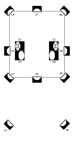
This uses the UQ-SSC-10 ten-channel matrix switching system with more
switching devices and
multiple decoders control device to be able to do these:
- Decode any matrix system,
- Play recordings with vertical sounnd components, and
- Play discrete recordings with the side images fixed.
The details of UQ-SSC-10 are here.
This form of separation enhancement uses extra speakers with acoustic
delays.
- It provides the missing clues that prevent side image localization.
Lack of these clues makes the ear find the speaker location instead of the sound location.
This system fixes the side localization problem.
The control boxes allow selecting the signal(s) most useful for providing
the delayed signal
to fix side localization.
These extra speakers are played at low levels.
- They are not used to carry primary sounds.
- They carry signals needed to steer human hearing.
- The treble of these signals is usually reduced.
- The only requirement for these sounds is that they reach the ear on the
other side of
the listener from the primary sound source.
- The sounds are delayed in my system by placing the speakers far behind
the listener.
There are many options available for enjoyment of surround sound:
- A new recording made in QS was released in 2018. It costs over $200, but comes with a working QS Variomatrix decoder on a PC board.
- New digital recordings are available in various formats (above)
- Purchase a home theater system. Most of them have a Dolby Surround decoder for old recordings and Dolby Digital for newer ones.
- Note that the "Dolby Surround" in newer systems is NOT the correct decoder for Dolby Surround recordings.
- Most DVDs and BluRays have discrete digital sound, and most have Dolby Surround for older systems.
- A new high separation matrix decoder called Surround Master is on the market. It can decode QS, SQ, and Dolby Surround.
-
Some new home theater systems have a system called Dolby Atmos. It has extra speakers on the ceiling for height effects. Older ones still play Dolby Surround.

Atmos 7.1.2
- Use a restored 1970s quadraphonic system.
- Use stereo components with a matrix decoder bought secondhand.
- Use stereo headphones to hear dichophony from RM or SQ recordings.
- Use a stereo that has separate speakers, an RM or QM speaker matrix, and add some speakers:
- New recordings exist in Dolby Surround. They play just fine on QS, EV, and
Dynaquad. You can't tell the difference between Dolby Surround and QS:
- Most stereo (analog outputs) soundtracks on DVDs are in Dolby Surround.
- Most stereo VHS tapes made after 1978 are in Dolby Surround.
- Most soundtrack albums after 1977 on LP, cassette, and CD are in Dolby Surround.
- Many other albums are recorded in Dolby Surround. Some are labeled as such.
- Search used record stores. pawnshops, and flea markets for used quadraphonic
recordings:
- Avoid CD-4 recordings, because the carriers on used records have probably been damaged.
- Angel records used a circle around the angel logo to show the recording is in SQ.
- A record that just says "quadraphonic" is probably in Stereo-4.
- Record your own surround sound:
All of these work with any of the RM or QM playback techniques above.
- Use the techniques for using a mixer to encode while recording musicians.
- Use the techniques for Live Recording Techniques while recording musicians.
- Use the techniques for Surround Fields while recording musicians.
- Combine the techniques for Surround Fields and using a mixer to encode while recording musicians.
- Play an existing recording through stereo or quadraphonic speakers and use the techniques for Surround Fields to make a surround recording of it. Put the special mic array where a listener would normally be.
- Combine some reverb panned to the rear into an existing recording
-
Most of the basic patents for quadraphonic systems and Dolby Surround have expired:
The patents for all of the matrix systems devised before 1985 have expired.
As of 2019, the only matrix systems still under patent are Ambisonics and Circlesurround.
So you can do any of these:
- Make and sell original matrix music recordings in any of the original matrix systems without paying any royalties for the encoding.
- Build any quadraphonic encoder or decoder according to 1970s designs (assuming you can get the parts).
- Sell any quadraphonic equipment you build.
Note, however, that the trademarks for the various systems are still in force.
EIAJ STANDARDS
RM - Regular Matrix (e.g. QS)
QM - Quadraphonic Matrix (e.g. EV)
PM - Phase Matrix (e.g. SQ)
UX - Uniform Matrix (e.g. BMX)
CD - Discrete (e.g. CD-4).What you can do:
- Tell your listeners which decoder to use
- Put the EIAJ abbreviations (right) on your recording labels
- Put the EIAJ abbreviations on your decoder switch positions
What you must not do (without permission until around 2053):
- Put the trademarked logos on your recordings
- Put the trademarked system names on your recordings
- Put the trademarked logos on equipment you sell
- Put the trademarked system names on equipment you sell
The following methods can be used to create surround sound for a live audience:
- Use the mixer techniques in using a mixer to encode to produce an RM or QM mix. Then decode it with a Dolby Surround decoder into 4 channels of house PA.
- Use the mixer techniques in using a mixer to encode to produce an RM or QM mix. Then use a stereo amp and decode it with a high-powered Dynaquad decoder into 4 speakers.
- Use either of the above techniques with encoded recordings and a live DJ.
- Use a 4-bus mixer to control which parts go to which of 4 channels of a house PA.
The following are panning philosophies I have collected or formulated over the 40+ years of surround sound.
- During an experiment in 1971, a sound engineer was asked to mix an SQ recording with equal sound coming from all directions. But when the record was played, there was a distinct frontness and backness to the music. One of the listeners suggested that the listeners turn their chairs around and listen facing the center back. The music definitely sounded backwards. It was impossible to make such a recording because people recognize the lead parts and expect them to be up front. 0
- The limitations of the stereo phonograph groove, stereo speakers, and quadraphonic
speaker locations put restrictions on where sounds can be put in a matrix recording (and
even a CD-4 recording):
- Lateral motion of the phono stylus can handle more bass than any of the other motions.
- Bass reproduction works best when the bass is in the front speakers in phase.
- Bass reproduction also works best on a 2-channel stereo when the bass is in phase in the speakers.
- Vertical stylus motions disappear in mono play and in mono FM radio reception.
- Without the side image reconstruction of Dolby Surround, Surrfield, or the UQ-8, any sound panned between the speakers on one side will not be heard in the wanted location.
- Most matrix systems require deep bass instruments, (bass guitar, string bass, tuba, and the kick drum) to be placed at center front. UMX in a record groove requires them to be centered in the room.
- Most matrix systems have phase integrity that enhances bass reproduction in only the left front and right front speakers. There are usually phase differences between the other pairs of speakers.
- When a matrix recording is played in 2-channel stereo, parts with deep bass will be weak if they are not in phase in the stereo speakers.
- In most matrix systems, it is not a good idea to place instruments at center back. Only UMX, UD4, Matrix H, UHJ, CD-4, Surrfield, and Spheround do not cause sounds placed at center back to disappear in mono play.
- Unless only Dolby Surround or UQ-8 will be used to play the recording, special techniques must be used to make panned sounds appear between the speakers on one side of the listener.
- There are several different philosophies on the best way to pan the parts in a
surround sound recording.
- Replicate the performance as though the listener is in the audience
- Use a combination of close, distant, and ambience mics.
- The Surrfield or Spheround system could be used for distant/ambience mics.
- Record the mics on a multitrack recorder.
- Pan the close mics near where the performers actually were.
- For best ambience performance with a matrix system, restrict the width of the performance stage to half the width between the front speakers.
- Create the performance as though the band is on a stage instead of in a studio
- Record the parts on a multitrack recorder.
- Create an ambient sound field with artificial delays and reverb.
- Play the parts into speakers in an empty auditorium and use a Surrfield or Spheround mic to get the ambience tracks.
- Pan the parts in a way that sounds like a live performance.
- Put the ambience behind the listener.
- Spread out the band into a tridemisemicircle (3/4 of a circle - or is it a
sesquisemicircle?).
- Record the parts on a multitrack recorder.
- Create a sound field with artificial delays and reverb.
- Pan the lead part, the bass, and the drums to center front.
- Pan the accompaniment parts to LF or RF.
- Pan harmony parts to L or R.
- Pan the delays and reverbs to LB and RB.
- Pan only one part to each position.
- Keep the drum kit together in one pan position.
- Put any ambience behind the listener.
- Surround the listener with sounds coming from all directions
- Record the parts on a multitrack recorder.
- For a string quartet, put one part in each speaker.
- Pan each part in a different direction.
- Pan the bass parts near CF.
- Expect parts panned to CB to disappear in mono play.
- Pan any delays and reverbs to CB.
- Pan only one part to each position.
- Separate the drum kit into many different parts.
- Follow the motions of the actions on a movie screen (e.g. Dolby Surround)
- Record the parts on a multitrack recorder or magnetic film.
- Use a film/sound editor to create the soundtrack to match the action in the picture.
- Replicate the performance as though the listener is in the audience
Part of the problem with surround sound is fitting into an average room. Actually, the biggest obstacle to overcome is a spouse who loves to rearrange the furniture periodically.
Here are some suggestions to ease the burden of having a quadraphonic or surround sound system in an average room:
- Mount speakers on the wall near the ceiling
- Put shelves around the room near the ceiling and set the speakers on them.
- Recessed ceiling or wall speakers
- Run the wires behind the baseboards
- Put the rest of the audio system in a different room
 In his book, "Four Channel Sound", Leonard Feldman had a
diagram 23 showing "apparent room sizes"
for the QS and old EV matrix systems. I wanted to display similar diagrams for all
matrix systems. So I developed a method to make
similar diagrams. The diagram for the original EV matrix is at right.
In his book, "Four Channel Sound", Leonard Feldman had a
diagram 23 showing "apparent room sizes"
for the QS and old EV matrix systems. I wanted to display similar diagrams for all
matrix systems. So I developed a method to make
similar diagrams. The diagram for the original EV matrix is at right.
I originally developed this idea in 1988, but the printer I was using quit in that year and I no longer have equipment needed to read the disks. So I had to re-create the design from memory in 2018.
The diagrams are on this page: Quadraphonic Systems
I have had several surround sound preferences over the years. Here they are with the reasons behind them:
| PREFERENCES AND REASONS | |||||||||||||||||
|---|---|---|---|---|---|---|---|---|---|---|---|---|---|---|---|---|---|
| REASONS FOR PREFERENCES | |||||||||||||||||
| PREFERRED | DISLIKED | Simpler | Inexpensive | Available | Compatible | Realism | Ambiance | Side Image | Other reasons | ||||||||
| Analog | digital | YES | no | YES | no | YES | no | YES | no | ? | ? | Better | lost | ? | ? | Legacy item | only new |
| Phonograph* | others | YES | no | even | even | YES | no | YES | no | ? | ? | ? | ? | ? | ? | Legacy gear | only new |
| Matrix | discrete | YES | no | YES | no | YES | no | YES | no | YES | no | ? | ? | ? | ? | Synth quad | no synth |
| RM | SQ | YES | no | YES | no | More | less | More | less | ? | ? | Better | low | Better | low | Hall amb. | low hall |
| RM | others | YES | no | YES | no | More | less | More | less | YES | no | Better | low | ? | ? | Field | twisted |
| Dolby PL | other RM | no | YES | some | some | YES | no | YES | no | YES | no | Better | low | Better | bad | Side pan | sides cog |
| Other Q4 | CD-4 | YES | no | YES | no | some | no | some | no | ? | ? | ? | noise? | ? | cog | Better | fails |
| Hardware disc | digital files | YES | no | ? | ? | low | High | More | less | ? | ? | ? | ? | ? | ? | Can keep | file loss |
| CD DVD audio | others | YES | no | YES | no | High | low | YES | no | ? | ? | ? | ? | ? | bad | Easy use | complex |
| DVD | BluRay | YES | no | YES | no | Yes | Yes | More | less | ? | ? | ? | ? | poor | poor | Easy use | complex |
| Dolby PL | Dolby Digital | YES | no | More | less | same | same | YES | no | ? | ? | ? | ? | Better | bad | Side pan | sides cog |
| DD 5.1 | DD 7.1 | YES | no | YES | no | same | same | More | less | ? | ? | ? | ? | bad | poor | Wide use | esoteric |
| RCA cables | HDMI | YES | no | YES | no | YES | YES | YES | no | ? | ? | ? | ? | ? | ? | Legacy gear | only new |
| Actual knobs | menus | YES | no | no | YES | ? | ? | ? | ? | ? | ? | ? | ? | ? | ? | Retain set | forget set |
I want the phonograph record to come back. And I want to always be able to have surround sound while using my Collaro Conquest.
I hate equipment that forgets everything when the power fails.