The details are essentially complete now.
Note that this decoder can be expensive to build. The page author was lucky to get
most of the parts at an auction.
- The Phasors
PART I - THE BASICS
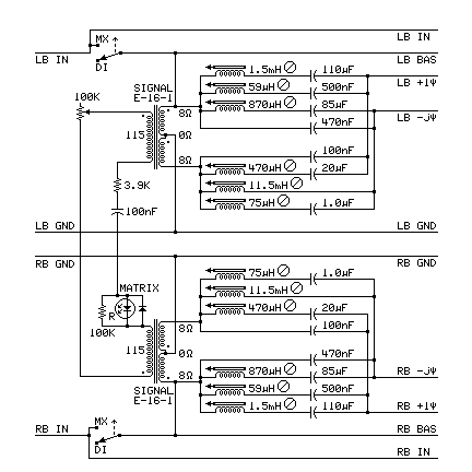
Phasor Set
Facts about how these phase-shifting networks were designed:
- The transformers were chosen to have higher current carrying capability.
- They must have many turns in the windings and low resistance.
- Adjustable inductors with tuning slugs were used to set the inductance values.
- The values of inductors and capacitors were set empirically to get the desired
results.
- A signal generator and an oscilloscope were used to set this up with the
speakers to actually be used with it.
- An oscilloscope verified that +1ψ and -jψ were always at 90° phase angle
to each other at all audio frequencies.
- The phasors are accurate from 30 Hz to 20 KHz.
- Capacitors were connected in series and/or parallel to get the needed values.
- Nonpolarized capacitors were used with at least 100 volt ratings.
- Inductors were chosen to have higher current carrying capability so they have
low resistance.
- The LED is used to show the likelihood of the presence of matrix-encoded material
in the incoming signal.
- The 100K resistor across the LED is not in the original design. It removes noise.
For all diagrams on this page:
- All unlabeled diodes are small-signal germanium diodes.
- DI = discrete
- MX = matrix
- HA = Hall Ambience
- DS = Dolby Surround.
- Basic Front Matrix Decoding
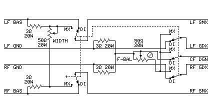
Front Decode
The front matrix decoder system:
- The two 3 Ω resistors and the 50 Ω WIDTH potentiometer on the signal
side form a voltage divider between the left channel and right channel signal feeds.
- The two 3 Ω resistors on the ground side make sure there is a common ground
between the front channels. It also provides the connection for the F-BAL adjustment.
- The F-BAL adjustment can widen the front WIDTH. It also is part of the Autovary
device (In the Autovary section). If Autovary is not installed, set it to 2 ohms.
- A former version of this had circuitry between the LF IN and LF BAS terminals and
between the RF IN and RF BAS terminals. These are now just wires.
- Adjustment of the WIDTH control sets the matrix decoding parameters for the front
channels. It sets the amount of blend between the front channels.
These are the values of the WIDTH control in ohms (assuming that 8-ohm speakers
are used):
| MATRIX |
Dsct | DQ | EV-4 | QS | SQ | EV-U |
UQ | CQ | HA | DS |
| WIDTH | byp | 50.0 Ω | 12.0 Ω | 4.25 Ω |
27.0 Ω | 12.0 Ω | 6.43 Ω | 5.33 Ω |
4.25 Ω | 50.0 Ω |
- Basic Back Matrix Decoding
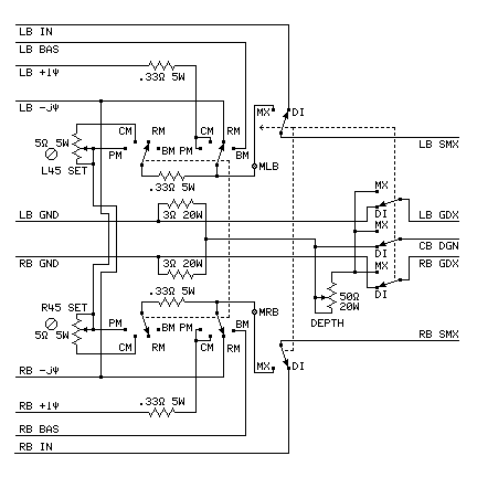
Back Decode
The back matrix decoder system:
- The Back Selector switch selects one of the four following general matrix types:
- BM - BASIC MATRIX - A matrix using sum and difference mixing, but no phase shifts
(e.g. EV4, DQ, and HA)
- RM - REGULAR MATRIX - A matrix using phase shifters to avoid phase problems
(e.g. QS)
- CM - COMPATIBLE MATRIX- Plays the other three kinds when mixed on a record changer
(e.g. CQ)
- PM - PHASE MATRIX - A matrix coding back signals as circular or elliptical stylus
motions
(e.g. SQ, SQB, EVU, UQE, and also UM, H, and HR)
- The phase switch (in the output controls section) selects the phase of the left back
channel to match the phase requirements of each matrix.
- The two 3 Ω resistors and the 50 Ω DEPTH potentiometer on the ground side
form a T bridge between the left channel and right channel speakers.
- The L45 and R45 adjustments adjust the phase of the 45 degree relative phase shift.
These set the phase for the back channels in the CM position.
- The ∅ indicates a screwdriver adjustment inside the case
or on the back panel.
- Note that the speakers must be connected for the back decoder to work.
If a speaker is disconnected the decoding angles are changed.
- Adjustment of the DEPTH control sets the matrix decoding parameters for the back
channels. It sets the amount of antiblend between the back channels.
These are the values of the DEPTH control in ohms (assuming that 8-ohm speakers are
used):
| MATRIX |
Dsct | DQ | EV-4 | QS | SQ | EV-U |
UQ | CQ | HA | DS |
| DEPTH | byp | 10.9 Ω | 32.0 Ω | 5.65 Ω |
5.33 Ω | 5.33 Ω | 3.75 Ω | 5.33 Ω |
50.0 Ω | 50.0 Ω |
- Basic Input and Output controls
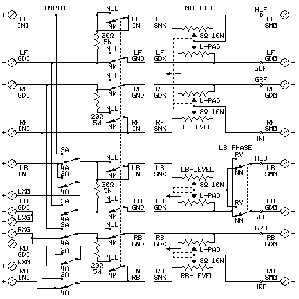
Input and Output
Basic Input Controls:
- The input Amplifier Selector selects whether a 2-channel amplifier or a 4-channel
amplifier will drive the decoder and speakers:
- 2A - A stereo (2 channel) amplifier is used drive the decoder and speakers
- 4A - A 4 channel amplifier (or two stereo amplifiers) drive the decoder and
speakers
- For discrete quadraphonic sound, the 4A position must be used.
- When only the 2-channel amplifier source is being used, the other two channels
are connected to the external outputs. If these are not used, 8Ω 20W resistors
should be connected to these outputs.
- The NUL switch is used to adjust the balance of the amplifiers. Select NUL, Play
a mono recording, and adjust the balance control of each stereo amplifier to get
minimum sound from the speakers. Then set the switch back to NM.
Basic Output Controls:
- The L-pads set the levels of the outputs to the speakers. The original UQ-44 has a
ganged pair of L-pads for the front channels, but the back channels each have their
own L-pads.
- The phase switch selects the phase of the left back channel.
- If the basic matrix selector is installed, the phase switch is changed to match
the phase requirements of each matrix according to the table below. It can also be
used to try different methods.
- If the preset matrix selector (below) is installed, the phase switch is
automatically correct in the NM position. In this case, the manual phase switch is
used to override the preset setting to try different methods.
- The circuit in the UMX and H Switches section diagram (below) is inserted at the
points ⊗ (right) labeled Hxx and Gxx (where xx is the
quadraphonic channel) in the output diagram.
- The Matrix Presets and the Speaker Orientation Rotation circuits (below) are inserted
in the circuit for UMX and H Switches (below).
- The settings of the Back Selector (in the basic back matrix section) and the Phase
Switch for each matrix are in the table below:
(Dsct = Discrete, HA = Hall Ambience, DS = Dolby Surround,
nm is lowercase to make other settings more visible)
| MATRIX |
Dsct | DQ | EV-4 | QS | SQ | EV-U |
UQ | CQ | HA | DS |
| SELECT |
DI | BM | BM | RM | PM | PM |
PM | CM | BM | RM |
| PHASE |
nm | nm | nm | RV | RV | RV |
RV | RV | nm | RV |
- Back Autovary
PART II - ADDING FEATURES †
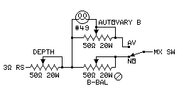
Back Autovary
Autovary increases separation between the channels based on
program material direction.
Autovary never suppresses the amount of ambience in a recording the way
gain-riding systems did.
No kind of pumping or other audible shifting of images occurs with
Autovary.
BELIEVE IT OR NOT, THIS PASSIVE DECODER HAS AUTOVARY
SEPARATION ENHANCEMENT WITHOUT AMPLIFIERS.
- This is inserted in place of the DEPTH control in the Basic Back Matrix
Decoding section above. Connect the circuit terminals to the places where the
DEPTH control connects.
- Use the AUTOVARY B control to set the amount of back Autovary effect.
- Select the correct lightbulb.
The #49 lightbulb has been discontinued. However, other bulbs are
available with the same characteristics. #48 is #49 with a different base.
Use the following procedure:
- - Multiply the channel power output in watts by the nominal speaker
impedance in ohms.
- - Take the square root of the above product to get the max useful
power output voltage.
- - Divide the max power output voltage by 5 to get the optimum
lightbulb voltage.
- You want a small instrument panel light, not a large
illumination lamp.
- The hot resistance should be between 25 and 35 ohms.
- If the amplifier burns out the bulb, get a bulb with a higher
voltage.
Sample light bulb values:
| BULB | VOLTS | AMPS | WATTS |
HOT OHMS | COLD OHMS | MAX AMP WATTS | BASE |
| #48 | 2 V | .06 A | .12 W |
33 | 3.3 | 20 W | Miniature Screw |
| #49 | 2 V | .06 A | .12 W |
33 | 3.3 | 20 W | Miniature Bayonet |
| #1490 | 3.2 V | .16 A | .512 W |
20 | 2.0 | 32 W | Miniature Bayonet |
| #44 | 6.3 V | .25 A | .1.6 W |
25 | 2.5 | 120 W | Miniature Bayonet |
| #51 | 7.5V | ..22 A | 1.65 W |
34 | 3.4 | 175 W | Miniature Bayonet |
- Buy spare bulbs. They might discontinue them.
- Set the B-BAL control to the minimum resistance of the lightbulb with an
ohmmeter.
- Front Autovary
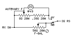
Front Autovary
Autovary increases separation between the channels based on program
material direction.
- This is inserted in place of the F-BAL control in the Basic Front Matrix
Decoding section above.
- Connect the circuit terminals to the places where the
F-BAL control connects.
- Use the AUTOVARY F control to set the amount of front Autovary effect.
- Use the same lightbulb type the Back Autovary uses.
- Set the F-BAL control to the minimum resistance of the lightbulb with an
ohmmeter.
- Front Autovary is not as effective as Back Autovary.
- Bass Booster
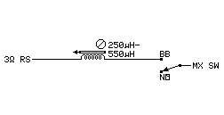
Bass Boost
The bass booster raises the level of bass (which is usually
nondirectional).
- It does this by sending all of the bass to all 4 speakers with no
matrix decoding.
- If the Basic Back Matrix Decoding section above is used as is,
- The Bass Booster is inserted in parallel with the DEPTH control.
- If the Back Autovary is used as is, The Bass Booster is connected to the same two
terminals in parallel with the Back Autovary circuit.
- If the Back Presets circuit is used, it should be added after the Back Autovary
and Bass Booster circuits are in place.
- Turn on the Bass Booster to send the deep bass to all four speakers.
- UMX and H Switches
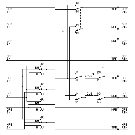
UMX and H
UMX and H Switch circuits:
- The H-UJ-HR Selector switch selects special matrix decoding:
- NM - NORMAL OPERATION - Uses the matrix selected by the Basic Back Matrix Decoding
section (above) or the Presets (below).
- H UJ - Modifies the SQ or PM Matrix selected in the Basic Back Matrix Decoding
section or the Presets to approximate either the BBC Matrix H or Ambisonic UHJ.
Also selects the correct phases for these matrices with the Phase switch set for PM
operation.
- HR - Modifies the SQ or PM matrix selected in the Basic Back Matrix Decoding section
or the Presets to approximate accidentally phase-reversed Matrix H. Also selects
the correct phases for this matrix with the Phase switch set for PM operation.
- The UM Selector switch selects other special matrix decoding:
- Do not select a special matrix on both of these switches at the same time. The matrix
so obtained is stupid (diagonally opposite speakers have the same signal).
- The phase switch selects the phase of the left back channel.
- If the basic matrix selector is installed, the phase switch is changed to match
the phase requirements of each matrix according to the table below. It can also be
used to try different methods.
- If the preset matrix selector (below) is installed, the phase switch is
automatically correct in the NM position. In this case, the manual phase switch is
used to override the preset setting to try different methods.
- The circuit for the UMX and H Switches section diagram (right) is inserted at the
points ⊗ labeled Hxx and Gxx (where xx is the
quadraphonic channel) in the output diagram (above).
- The signals come into the Hxx IN and Gxx IN terminals in this
diagram.
- The signals go out of the Hxx RTN and Gxx RTN terminals in this
diagram.
- One of the circuits for the Matrix Presets section diagram (below) is inserted at
the points ⊗ labeled PLB and CLB in the UMX and H
diagram (right).
If Presets are not used, the portion of the DI-MX switch on this
page can be omitted.
- The circuit for the Speaker Orientation section diagram (below) is inserted at the
points ⊗ labeled Txx and Nxx (where xx is the
quadraphonic channel) in the output diagram (right).
- The settings for UQ-44 using the Back Select circuit for each matrix are in the
table below:
(Dsct = Discrete, HA = Hall Ambience, DS = Dolby Surround,
nm is lowercase in the table to make other settings more visible)
| MATRIX |
Dsct | DQ | EV-4 | QS | SQ | EV-U |
UQ | CQ | HA | H | UJ | HR | UM |
DS | BM | RM | PM | CM |
| BACK SELECT |
DI | BM | BM | RM |
PM | PM |
PM | CM | BM | PM |
PM | PM | PM |
RM | BM | RM | PM | CM |
| WIDTH KNOB |
byp | 50.0 Ω | 12.0 Ω | 4.25 Ω |
27.0 Ω | 12.0 Ω | 6.43 Ω | 5.33 Ω |
4.25 Ω |
27.0 Ω | 12.0 Ω | 27.0 Ω | 50.0 Ω |
50.0 | set | set | set | set |
| DEPTH KNOB |
byp | 10.9 Ω | 32.0 Ω | 5.65 Ω |
5.33 Ω | 5.33 Ω | 3.75 Ω | 5.33 Ω |
50.0 Ω |
0.00 Ω | 0.00 Ω | 0.00 Ω | 0.00 Ω |
50.0 | set | set | set | set |
| H-UJ-HR SELECT |
nm | nm | nm | nm | nm | nm |
nm | nm | nm | H | UJ | HR | nm |
nm | nm | nm | nm | nm |
| UM SELECT |
nm | nm | nm | nm | nm | nm |
nm | nm | nm | nm | nm | nm | UM |
nm | nm | nm | nm | nm |
| PHASE (Back Select) |
nm | nm | nm | RV | RV | RV |
RV | RV | nm | RV | RV | RV | RV |
RV | nm | RV | RV | RV |
- Front Phased Crossblend (partly cures side-imaging problem)
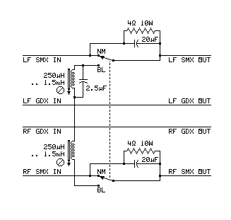
Front Crossblend
Front Phased Crossblend:
- This is inserted in the front channels at the point between the front matrix
decoder outputs (SMX and GDX) and the output section.
- This was a modification of the Bauer headphones circuit.
It provides cross signals that make the speakers act more like
headphones.
- This causes a crossblend between the front channels with a slight delay
in the process. This helps with the side-imaging problem.
- This circuit was added as an experiment. It is not necessary for normal
decoding purposes.
- This circuit was an attempt to make a stable side image and further
stabilize the front image.
- The idea was to make it hard for the listener to find the speakers themselves.
- The idea behind this circuit didn't work very well.
- This circuit would work better if there was a phase reversal in it.
- Adjustment of this crossblend is done by adjusting the two inductors.
They are adjusted so the blend is slight at mid frequencies and the delay is
maximized.
This was done by ear. Without an inductance bridge,
the exact values cannot be recovered.
- Turn on the crossblend to synthesize a front field.
- Back Filter (for Dolby Surround)
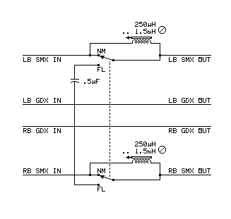
Back Filter
Back Low-Pass Filter
- This is inserted in the back channels at the point between the back matrix
decoder outputs (SMX and GDX) and the output section.
- This provides the low-pass filter needed to properly decode Dolby surround
recordings.
- This keeps the center front dialogue leakage out of the surround channel.
- Adjustment of this filter is done by adjusting the two inductors.
They are adjusted so that center back signals are filtered out above
7 KHz.
- The two inductors must be set to the same value.
This can be done by ear with a mono record.
Balance the two channels to sound equal.
- If an impedance bridge is available, set the inductors to 1 mH.
- An alternate circuit uses two .5 uF capacitors, with each one connected to
its switch and to the GDX line on the same channel.
In this case, leave out the capacitor between the two FL positions on the
switch.
- This can be used to remove record noise from the back channels.
This is useful when new and old (especially mono) records are mixed together
in a stack on a record changer.
- Turn on the Back Filter to remove out-of-phase sound above 7 KHz.
- Headphone Circuits
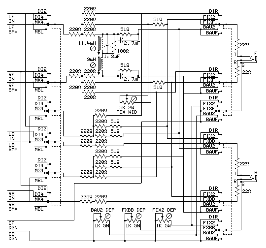
Headphones
This works with 2-speaker or 4-speaker headphones.
There are three controls.
The Headphone Input selector has 4 positions:
- DI2 selects a 2-channel source.
- DI4 selects a 4-channel discrete source.
- MX4 selects a 4-channel decoded matrix source.
- MBL selects a 4-channel decoded matrix blend.
The Front Headphone Mode selector has 5 positions:
- DIR passes unaltered sound from the source.
- FIX2 Fixler-decodes a 2-channel signal.
- FIXF Fixler-decodes a 4-channel front signal.
- BAU2 Bauer-decodes a 2-channel signal.
- BAUF Bauer-decodes a 4-channel front signal.
The Back Headphone Mode selector has 5 positions:
- DIR passes unaltered sound from the source.
- FIX2 Fixler-decodes a 2-channel signal.
- FXBB decodes a 4-channel back signal for Fixler or Bauer.
- BAU2 Bauer-decodes a 2-channel signal.
- BAUF Bauer-decodes a 4-channel front signal.
Notes:
- All unspecified resistors are rated 0.5 watt.
- The Fixler Headphone System was invented by Jon Fixler.
- The Bauer Headphone System was invented by Benjamin Bauer.
- This circuit cannot work with UMX, BMX, Matrix H, HR, or UJ.
- This circuit was redesigned from the original UQ44 design, which was
not nearly as useful.
The following table shows the switch positions for the desired use
of the headphones:
| DESIRED FUNCTION |
PHONES |
DIRECT TO PHONES |
FIXLER ENCODE |
BAUER ENCODE |
| TYPE | # Sets |
INPUT | F OUT | B OUT |
INPUT | F OUT | B OUT |
INPUT | F OUT | B OUT |
| HEAR UNCHANGED STEREO | 2 ch | 1 or 2 |
DI2 | DIR | DIR |
DI2 | FIXF | FIXF | DI2 | BAUF | BAUF |
| HEAR ENHANCED STEREO | 2 ch | 1 or 2 |
DI2 | DIR | DIR |
DI2 | FIX2 | FIX2 | DI2 | BAU2 | BAU2 |
| HEAR DECODED MATRIX | 2 ch | 1 or 2 |
MBL | DIR | DIR |
MBL | FIX2 | FIX2 | MBL | BAU2 | BAU2 |
| HEAR DISCRETE QUAD IN 2-CH PHONES* | 2 ch | 1 or 2 |
MBL | DIR | DIR |
MBL | FIX2 | FIX2 | MBL | FIX2 | FIX2 |
| HEAR UNCHANGED STEREO IN 4-CH PHONES | 4 ch | 1 |
DI2 | DIR | DIR |
DI2 | FIXF | FIXF | DI2 | BAUF | BAUF |
| HEAR ENHANCED STEREO IN 4-CH PHONES | 4 ch | 1 |
DI2 | DIR | DIR |
DI2 | FIXF | FXBB | DI2 | BAUF | FXBB |
| HEAR DISCRETE QUAD | 4 ch | 1 |
DI4 | DIR | DIR |
DI4 | FIXF | FXBB | DI4 | BAU2 | FXBB |
| HEAR DECODED MATRIX QUAD | 4 ch | 1 |
MX4 | DIR | DIR |
MX4 | FIXF | FXBB | MX4 | BAUF | FXBB |
* The DI-MX switch must be set to DI.
- Matrix Presets
PART III - FUN STUFF †
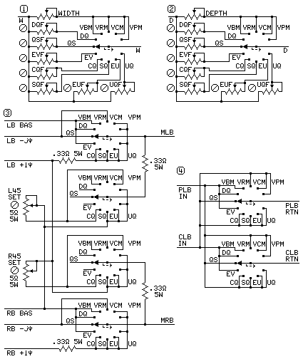
Matrix Presets
The presets provide the correct settings for each matrix without
the user having to fiddle with settings when switching between matrix systems.
- There is a set of preset settings for each of the 7 matrices the selector switch
has a position for.
Those positions are (DQ, QS, EV, CQ, SQ, EU, and UQ).
- Each such position has a preset setting for WIDTH and DEPTH.
- There ARE 4 more positions on the switch that use the front panel WIDTH and DEPTH
controls.
- The VBM position replaces the BM on the original switch above.
It provides an adjustable basic sum-and-difference matrix
(for DQ, EV, and HA).
- The VRM position replaces the RM on the original switch above.
It provides an adjustable regular matrix or QM matrix
(for QS).
- The VCM position replaces the CM on the original switch above.
It provides an adjustable RM-SQ compatible matrix
(for CQ).
- The VPM position replaces the PM on the original switch above.
It provides an adjustable PM phase matrix
(for SQ, EU, UQ, and also UM, H, and HR).
- Build the entire rest of UQ44 before adding the presets in the circuitry.
But leave room in the case for the PRESET switch and the preset
potentiometers.
- The ∅ indicates a screwdriver adjustment inside
the case or on the back panel.
- Part 1 replaces the WIDTH control in the front decode circuit (W-W).
The existing 20 Ω 50 W WIDTH control connects to this circuit as shown.
All ∅ potentiometers in part 1 are 20 Ω 50 W
- Part 2 replaces the DEPTH control in the back decode circuit (D-D).
The existing 20 Ω 50 W DEPTH control connects to this circuit as shown.
All ∅ potentiometers in part 2 are 20 Ω 50 W
- Part 3 replaces the entire back matrix section with the 4-position selector
to the left of the points ⊗
labeled MLB and MRB. The new switch replaces the 4-position switch.
- Part 4 is inserted into the left back circuit in the UMX and H Switches section at
the points ⊗
labeled PLB and CLB. UMX and H must be installed to install presets.
- The settings for UQ-44 using Presets for each matrix are in the table below:
(Dsct = Discrete, HA = Hall Ambience, DS = Dolby Surround,
control other than preset,
nm is lowercase in the table to make other settings more visible)
| MATRIX |
Dsct | DQ | EV-4 | QS |
SQ | EV-U | UQ | CQ |
HA | H |
UJ | HR |
UM | DS |
BM | RM |
PM | CM |
| MATRIX PRESET |
DI | DQ | EV-4 | QS |
SQ | EV-U | UQ | CQ |
BM | PM |
PM | PM |
PM | RM |
BM | RM |
PM | CM |
| PRESET WIDTH |
byp | 50.0 Ω | 12.0 Ω | 4.25 Ω |
27.0 Ω | 12.0 Ω | 6.43 Ω | 5.33 Ω |
4.25 Ω | 27.0 Ω |
12.0 Ω | 27.0 Ω |
50.0 Ω | 50.0 Ω |
Knob | Knob |
Knob | Knob |
| PRESET DEPTH |
byp | 10.9 Ω | 32.0 Ω | 5.65 Ω |
5.33 Ω | 5.33 Ω | 3.75 Ω | 5.33 Ω |
50.0 Ω | 0.00 Ω |
0.00 Ω | 0.00 Ω |
0.00 Ω | 50.0 Ω |
Knob | Knob |
Knob | Knob |
| H-UJ-HR SELECT |
nm | nm | nm | nm |
nm | nm | nm | nm |
nm | H |
UJ | HR |
nm | nm |
nm | nm |
nm | nm |
| UM SELECT |
nm | nm | nm | nm |
nm | nm | nm | nm |
nm | nm |
nm | nm |
UM | nm |
nm | nm |
nm | nm |
| PHASE CONTROL |
nm | nm | nm | nm |
nm | nm | nm | nm |
nm | nm |
nm | nm |
nm | nm |
nm | nm |
nm | nm |
- Speaker Orientation Rotation (as on Sansui QS-1)
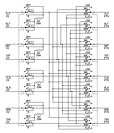
Speaker Orientation
This can also be built as an outboard add-on unit that hooks up
to the speaker outputs of any quadraphonic system.
It can also be built without the output selector switch for just the
rotation function.
Output Selector
- OFF - The speakers are turned off.
- The amplifiers are loaded to prevent damage.
- Use this for headphone listening.
- F - The front speakers are on. The back speakers are turned off.
- This removes back instruments to compare.
- ALL - All speakers are turned on.
- This is the normal position.
- B - The back speakers are on. The front speakers are turned off.
- This removes front instruments to compare.
Output Rotator
- 180° - Quadraphonic image is turned halfway around.
- This is like facing the audience at the lectern.
- This compares front and back instrument placement.
- 90°L - Quadraphonic signals rotated to the left by 90°
- This is like sitting in left-side box seats.
- 0° - This is the normal position of the quadraphonic signals.
- 90°R - Quadraphonic signals rotated to the right by 90°
- This is like sitting in right-side box seats.
- FLIP - the front and back quadraphonic signals are exchanged on each side
- This is like facing the orchestra while upside down.
- This compares front and back instrument placement.
- Oscilloscope output for 4-channel display
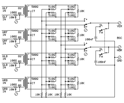
Oscilloscope
The display on the screen looks just like the Technics scope, but
works with any oscilloscope with X-Y input.
This can also be built as an outboard add-on unit that hooks up
to the speaker outputs of any quadraphonic system.
- This is connected to points Hxx and Gxx (where xx is the channel name)
in the Output diagram.
- This is just after the L-pads.
- This is connected just before the UMX and H Switches.
- The F+ / B+ and L+ / R+ switches match the polarity of the outputs to the
oscilloscope inputs.
- Set them so front and left face in the desired directions on the screen.
- These are either inside the case or on the back panel as the builder
desires.
- The SL / FA switch selects slow or fast response.
- This is put on either the front panel or the back panel as the builder
desires.
- All of the diodes in this diagram are germanium diodes with at least 50
Peak Reverse Volts.
- The oscilloscope screen edge centers and corners are labeled as follows:
- Use the vertical and horizontal centering controls to put the spot on the center.
- Do not leave the oscilloscope on without any music playing.
- Front Panel
PART IV - PANEL LAYOUT
Here is how the page author designed the front panel:
MATRIX
PRESET |
|
AUTOVARY
F LIGHT |
|
AUTOVARY
B LIGHT |
|
SPEAKER
SELECT |
|
WIDTH
CONTROL |
|
MATRIX
LIGHT |
|
DEPTH
CONTROL |
|
MATRIX
DISCRETE |
|
AUTOVARY
F SET |
|
AUTOVARY
B SET |
|
SPEAKER
ROTATE |
|
LB
LEVEL |
|
FRONT
LEVEL |
|
RB
LEVEL |
|
|
AUTOVARY
ON |
FRONT
BLEND |
MATRIX
PHASE |
BACK
FILTER |
BASS
BOOST |
|
INPUT
SELECT |
|
FRONT
HP SEL |
F B
HP JACKS |
BACK
HP SEL |
|
HEADPHONES
INPUT SEL |
† These are not necessary for the operation of the basic decoder.
 Here are the details.
 Here are the details.


