This page explains the mathematics behind the quadraphonic matrix systems. The mathematic principles used are based on algebra, complex numbers, and trigonometry.
Calculating decibels:
The formulas in this section are in Microsoft Excel ® form.
Value_dB = 20 * log10(voltage_ratio)
Procedure: Find the common logarithm of voltage_ratio. Then multiply by 20.
Value_dB = 10 * log10(power_ratio)
Procedure: Find the common logarithm of power_ratio. Then multiply by 10.
voltage_ratio = 10 ^ (Value_dB /20)
Procedure: Divide Value_dB by 20. Then raise 10 to the power of the result.
power_ratio = 10 ^ (Value_dB /10)
Procedure: Divide Value_dB by 10. Then raise 10 to the power of the result.
In quadraphonics, this would be 4 equations in 4 unknowns - a discrete quadraphonic system.
Such a system can have no solution. But such systems are not used in quadraphonics.
In quadraphonics, this would be 2 equations in 4 unknowns.
In quadraphonics, this would be 4 equations in 2 unknowns.
Modulations on the stereo record groove are defined by the RIAA (Recording Industry Association of America).
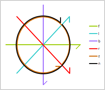
Here are the stereophonic groove modulations as defined by the RIAA:
Stereo Groove Modulations
These modulations are as viewed from beyond the cartridge end of a normally mounted pickup arm:
The left channel is recorded on the side of the groove closest to the
spindle.
- Left channel modulations slope up to the right and down to the left at a
45° angle (cyan).
The right channel is recorded on the side of the groove closest to the
rim.
- Right channel modulations slope up to the left and down to the right at a
45° angle (red).
In-phase modulations are lateral (horizontal - olive). They emulate a monaural record.
Reversed phase modulations are vertical (violet).
Clockwise motion (viewing the cartridge end of the tonearm) occurs when the left channel leads the right channel by 90° (black).
Anticlockwise motion (viewing the cartridge end of the tonearm) occurs when the left channel lags the right channel by 90° (brown).
Collaro size feeler
- Special equipment (including a special pickup cartridge) must not be needed to play the recording in stereo.
- Very few people will buy a recording not compatible with normal stereo equipment.
Only quadraphonic enthusiasts would be able to use it. So it is essential to make recordings fully playable on stereo players.
These rules ensure compatibility:
- This is necessary to keep from overloading one side of the stereo recording.
- The encoding and decoding methods should accomplish this.
- This is so the two stereo speakers will aid each other in reproducing the bass.
- At least two of the quadraphonic speakers should be in phase to aid each other in reproducing the bass.
- In addition, if the recording is on a phonograph record, the bass must be recorded laterally (in phase) in the groove.
Bass recorded in other orientations must be recorded at much lower levels to avoid overcutting the groove.
- This is a problem with most encoding systems.
- Usually the recording engineer is advised to not pan important material to center back.
Center back is a good place to hide some extra reverb.
- Large phase differences make a weird "phasiness" sensation when playing the recording in stereo.
- This effect makes image location of musical parts difficult.
- This unwanted effect happens with the UMX (BMX), Matrix H, Matrix E, Matrix G, and Phase Location.
- Note that while the matrix decoder removes phase anomalies when decoding the record, the stereo player does not.
- It is not advisable to use a matrix encoding system that shifts the phase of the front channels.
- A radio-frequency carrier in the groove causes a swooping sound when a phonograph record is static-cued or slip-cued.
Radio-frequency carriers should not be used.
Nothing in the encoding and decoding system may change the basic waveforms that are encoded. This means that the following mathematical operations must not be used on the signals:
* Except where the trigonometric value is a constant used in a polynomial expression to define an encoding angle.
The process used for quadraphonic matrix is called matrix multiplication.
The following are the matrices used for one encode and one decode operation in matrix quadraphonics:
Here is an example of this use of the matrix. The Electro-Voice Stereo-4 System is shown. But it works for any matrix system.
ENCODER | DECODER | ||||||||||||||||||||||||||||||||||||||||||||||||||||||||||||||||||||||||||||||||||||||||||||||||||||||||||||||||||||||||||||||||||||||||||||||||||||||||||||||||
|
|
The procedure used to calculate this is found at the matrix multiplication page.
The rules of complex mathematics;
|
||
|
|
|
Groove Modulations
On Poincaré Sphere
The Poincaré Sphere was originally conceived by Henri Poincaré ("on-REE pwan-car-RAY") in 1892 to describe polarized light.
It is also called the Stokes Sphere, the Foucault Sphere, and the Fresnel Sphere.
Foucault ("foo-CO") used it to describe free-swinging pendulum motion.
Stokes and Fresnel ("freh-NELL") independently discovered its use for polarized light.
Scheiber and Robinson independently discovered its use in matrix quadraphonic signals.
The quadraphonic stylus motions are analogous to the Foucault pendulum motions.
The Poincaré Sphere represents the two channels of a stereo recording.
It represents stylus motions on a phonograph record, and signal relationships in other media.
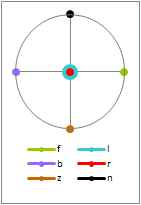
The diagrams (right) are as follows:
These are the descriptions of the six orthogonal motions and their positions on the Poincaré Sphere:
Great Circle
Any plane passing through the center of the Poincaré Sphere produces a great circle where it intersects the Poincaré Sphere.
The following matrix systems are examples of Great-Circle Matrix systems.
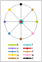
The order of the listed colors in the table shows the movement on this Poincaré sphere (shown at right) of a sound panned clockwise around the listener starting at the front.
Large spots are on the far side of the sphere.
MATRIX | ORIENTATION | COLORS ON DIAGRAM AT RIGHT | ||||
---|---|---|---|---|---|---|
FRONT | RIGHT | BACK | LEFT | FRONT | ||
QS, Stereo-4, Dynaquad | Equator | olive | red | violet | cyan | olive |
UMX and BMX | Opposite Meridians | black | red | brown | cyan | black |
BBC Matrix H (see below) | 45° diagonal | tan | red | blue | cyan | tan |
Matrix HR (see below) | 45° opposite diagonal | pink | red | yellow | cyan | pink |
Phase Location (Denon experiment) | Opposite Meridians | olive | brown | violet | black | olive |
Most other matrix systems are not great-circle systems.
The relative phase angles are as follows:
Poincaré Sphere
Corollary 1 to Postulate 3: Finding the great-circle distance between two points on the Poincaré Sphere:
The following formula calculates the geodesic distance between two points on the surface of the sphere.
This geodesic distance gives a central angle, which is used in the formulas below:
The variables:
The calculations:
Examples of orthogonal pairs (see diagram above):
Proof for the following three orthogonal pairs:
These are the original left and right encoded channels, recorded in the left wall and the right of the stereo record groove using the Westrex 45/45 process.
Since no signal processing was done before making the recording, they are still the original unchanged L and R signals from the quadraphonic encoder.
L' = L | R' = R |
The created orthogonal signals are signals from a sum and difference matrix: | |
H = 0.71 L + 0.71 R | V = 0.71 L − 0.71 R |
This orthogonal pair is used for FM multiplex stereo. | |
The original signals are recovered using a sum and difference matrix: | |
L' = 0.71 H + 0.71 V | R' = 0.71 H − 0.71 V |
L' = 0.71 (0.71 L + 0.71 R) + 0.71 (0.71 L − 0.71 R) | R' = 0.71 (0.71 L + 0.71 R) − 0.71 (0.71 L − 0.71 R) |
L' = 0.5 L + 0.5 R + 0.5 L − 0.5 R | R' = 0.5 L + 0.5 R − 0.5 L + 0.5 R |
L' = L | R' = R |
The created orthogonal signals are signals from a quadrature matrix: | |
A = 0.71 L + 0.71 Rj | B = 0.71 R + 0.71 Lj |
The original signals are also recovered using a quadrature matrix: | |
L' = 0.71 A − 0.71 Bj | R' = 0.71 B − 0.71 Aj |
L' = 0.71 (0.71 L + 0.71 Rj) − 0.71j (0.71 R + 0.71 Lj) | R' = 0.71 (0.71 R + 0.71 Lj) − 0.71j (0.71 L + 0.71 Rj) |
L' = 0.5 L + 0.5 Rj + 0.5 L − 0.5 Rj | R' = 0.5 R + 0.5 Lj + 0.5 R − 0.5 Lj |
L' = L | R' = R |
Proof: Any monophonic signal taken from 2-channel program material must be at some location on the Poincaré Sphere.
Because of this, any material at the point orthogonal to the point used must completely disappear from the monophonic signal.
The usual way to create a mono signal from a stereo signal is to use this sum:
M = 0.71 L + 0.71 R
But the following signal is entirely absent from the mono signal:
0.71 L - 0.71 R
Sansui used the sum of all of the decoder outputs, which reproduced the clockwise stylus motion and other motions that put sound into the clockwise reproduction
The anticlockwise stylus motion (not usually used) fully disappears from this signal.
At least one version of each sound will be picked up at an angle where it will be plainly decoded.
The following are true of any two points on the Poincaré Sphere:
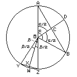
Poincaré Sphere Separations
Example 1:
- Note that when ∠α is 0°, cos(α/2) = 1.
- Note that when ∠α is 180°, cos(α/2) = 0.
Example 2:
- Note that when ∠β is 0°, cos(β/2) = 1.
- Note that when ∠β is 180°, cos(β/2) = 0.
Here are some of the commonly used values:
Sphere Angle | 0 | 30 | 39 | 45 | 54 | 60 | 82 | 90 | 109 | 120 | 133 | 135 | 143 | 150 | 151 | 160 | 169 | 176 | 179 | 180 |
---|---|---|---|---|---|---|---|---|---|---|---|---|---|---|---|---|---|---|---|---|
Crossfeed | 1.00 | 0.97 | 0.94 | 0.92 | 0.89 | 0.87 | 0.75 | 0.71 | 0.58 | 0.50 | 0.40 | 0.38 | 0.32 | 0.26 | 0.25 | 0.18 | 0.10 | 0.03 | 0.01 | 0.00 |
Separation dB | 0.0 | -0.3 | -0.5 | -0.7 | -1.0 | - 1.2 | - 2.5 | -3.0 | -4.7 | -6.0 | -8.0 | -8.3 | -10.0 | -11.7 | -12.0 | -15.0 | -20.0 | -30.0 | -40.0 | -60.0 |
Front separation:
Back separation:
Front to back separation:
Front separation:
Back separation:
Front separation:
Back separation:
Mono to back separation:
Back attenuation:
Any position attenuated more than 10 dB effectively disappears from mono playback.
Here are separations calculated using these methods.
Procedure:
C = cos(α/2)
Procedure:
S = 20 log10(C)
Procedure:
S = 20 log10(cos(α/2))
Procedure:
C = 10^(S/20)
Procedure:
α = 2 arccos(C)
Procedure:
α = 2 arccos(10^(S/20))
Calc on Sphere
Calculation 7: Calculate L and R signal outputs to encode a desired position C on the Poincaré sphere:
The colors in this list apply to only the diagram at right.
The angle θ (theta) is the angle from the L pole (cyan) of the sphere to the desired point C.
The angle θ is also the angle from the R pole (red) of the sphere to the corresponding desired point C'.
C' is 180°-θ from the L pole.
The angle ø (phi) is the phase angle between L and R on the equator of the sphere, where:
The angle ρ (rho) is a phase shift added so the encoded signal has a wanted phase relationship to other signals.
The angles are converted into encoding sine-cosine variable pairs:
The left-side left and right encoding outputs for point C, using signal x, is:
L = atx R = bftx
The corresponding mirror-image right-side left and right encoding outputs for point C', using signal y, is:
L = bfty R = aty
Obtain the same angles used in the encoding equations above.
The angle θ (theta) is the angle from the L pole (cyan) of the sphere to the desired point D.
The angle θ is also the angle from the R pole (red) of the sphere to the corresponding desired point D'.
D' is 180°-θ from the L pole.
The angle ø (phi) is the phase angle between L and R on the equator of the sphere, where:
The angle ρ (rho) is a phase shift added so the encoded signal has a wanted phase relationship to other signals.
The angles are converted into decoding sine-cosine variable pairs:
The decoding output for point D, using signals L and R, is:
U = atL + bftR
The corresponding mirror-image decoding output for point D', using signals L and R, is:
V = bftL + btR
In these equations, a, b, c, and d are values between -1 and 1.
In these equations, s and t are sign values of +1 or -1. Variable s goes with X, and t goes with Y.
In these equations, u and v are sign values of +1 or -1. Variable u goes with L, and v goes with R.
In these equations, m and n are sign values of +1 or -1. Variable m goes with Lj, and v goes with Rj.
For the encoding of any pair of symmetric signals, the following equations are used:
For the decoding of any pair of symmetric signals, the following equations are used:
Examples include the following matrix systems:
PAIR | a | b | c | d | s | t | u | v | m | n |
---|---|---|---|---|---|---|---|---|---|---|
lf and rf | 0.92 | 0.00 | 0.38 | 0.00 | +1 | +1 | +1 | +1 | +1 | +1 |
lb and rb | 0.00 | 0.92 | 0.00 | 0.38 | +1 | +1 | +1 | -1 | +1 | +1 |
Encoding equations:
Decoding equations:
PAIR | a | b | c | d | s | t | u | v | m | n |
---|---|---|---|---|---|---|---|---|---|---|
lf and rf | 1.00 | 0.00 | 0.00 | 0.00 | +1 | +1 | +1 | +1 | +1 | +1 |
lb and rb | 0.00 | 0.71 | 0.71 | 0.00 | -1 | +1 | +1 | +1 | +1 | +1 |
Encoding equations:
Decoding equations:
PAIR | a | b | c | d | s | t | u | v | m | n |
---|---|---|---|---|---|---|---|---|---|---|
lf and rf | 0.85 | 0.35 | 0.35 | 0.15 | +1 | +1 | +1 | +1 | +1 | -1 |
lb and rb | 0.35 | 0.85 | 0.15 | 0.35 | +1 | +1 | +1 | +1 | -1 | +1 |
Encoding equations:
Decoding equations:
Note the following special values in the above matrices:
No matter which great-circle matrix is used, there is at least one point where panning must be interrupted for a phase change as the sound is panned completely around the listener:
No matter which great circle is used, either the phase is continually changed as the signal is panned, or the phase must be changed at some point.
If all of the phase changes are at zero crossings, then the final phase of the signal after the panning will be reversed from the original signals before the panning, as shown here:
DIR | F | RF | R | RB | B | LB | L | LF | F |
---|---|---|---|---|---|---|---|---|---|
L | 0.71 | 0.38 | 0.00 | −0.38 | −0.71 | −0.92 | −1.00 | −0.92 | −0.71 |
R | 0.71 | 0.92 | 1.00 | 0.92 | 0.71 | 0.38 | 0.00 | −0.38 | −0.71 |
Examples of systems with planned holes:
The red bar shows the encoding phase hole:
DIR | F | RF | R | RB | B | B | LB | L | LF | F | |
---|---|---|---|---|---|---|---|---|---|---|---|
L | 0.71 | 0.38 | 0.00 | −0.38 | −0.71 | 0.71 | 0.92 | 1.00 | 0.92 | 0.71 | |
R | 0.71 | 0.92 | 1.00 | 0.92 | 0.71 | −0.71 | −0.38 | 0.00 | 0.38 | 0.71 |
The orange bars are where the bus selector is changed when panning:
DIR | F | RF | R | R | RB | B | LB | L | L | LF | F | ||
---|---|---|---|---|---|---|---|---|---|---|---|---|---|
L | 0.71 | 0.38 | 0.00 | −0.00 | −0.38 | −0.71 | −0.92 | −1.00 | 1.00 | 0.92 | 0.71 | ||
R | 0.71 | 0.92 | 1.00 | 1.00 | 0.92 | 0.71 | 0.38 | 0.00 | 0.00 | 0.38 | 0.71 |
The orange bars show the encoding phase holes, automatically adjusted by phasors in the encode equations:
DIR | F | RF | R | R | RB | B | LB | L | L | LF | F | ||
---|---|---|---|---|---|---|---|---|---|---|---|---|---|
L | 0.71 | 0.38 | 0.00 | 0.00j | 0.38j | 0.71j | 0.92j | 1.00j | 1.00 | 0.92 | 0.71 | ||
R | 0.71 | 0.92 | 1.00 | −1.00j | −0.92j | −0.71j | −0.38j | −0.00j | 0.00 | 0.38 | 0.71 |
The orange bars show the encoding phase holes. It is unknown how they were implemented in practice:
DIR | F | RF | R | R | RB | B | LB | L | L | LF | F | ||
---|---|---|---|---|---|---|---|---|---|---|---|---|---|
L | 0.50 | 0.26 | 0.00 | 0.00 | 0.26 | 0.50 | 0.65 | 0.71 | 0.71 | 0.65 | 0.50 | ||
Lj | 0.50j | 0.26j | 0.00j | −0.00j | −0.26j | −0.50j | −0.65j | −0.71j | 0.71j | 0.65j | 0.50j | ||
R | 0.50 | 0.65 | 0.71 | 0.71 | 0.65 | 0.50 | 0.26 | 0.00 | 0.00 | 0.26 | 0.50 | ||
Rj | −0.50j | −0.65j | −0.71j | 0.71j | 0.65j | 0.50j | 0.26j | 0.00j | −0.00j | −0.26j | −0.50j |
Most matrix systems that are not great circle matrix systems also have at least one point where panning must be interrupted for a phase change as the sound is panned completely around the listener.
Example: Scheiber system and Sansui QS:
Value | Original system | × | Resulting System |
|
---|---|---|---|---|---|---|---|---|
System | Scheiber | QS | System | QS | Scheiber | |||
Major Value | 0.92 | × 1.08 = | 1.00 | Major Value | 1.00 | × 0.92 = | 0.92 | |
Minor Value | 0.38 | × 1.08 = | 0.41 | Minor Value | 0.41 | × 0.92 = | 0.38 | |
Resultant Value | 1.00 | × 1.08 = | 1.08 | Resultant Value | 1.08 | × 0.92 = | 1.00 |
The procedure to find out what to multiply the original system coefficients by to get the resulting system is:
Percent Blend | Major is 1.00 | Result is 1.00 | Encode Angle | ||
---|---|---|---|---|---|
Minor | Result | Major | Minor | Stylus θ | |
100% | 1.00 | 1.41 | 0.71 | 0.71 | 45.0° |
80% | 0.80 | 1.28 | 0.78 | 0.62 | 38.7° |
50% | 0.50 | 1.12 | 0.89 | 0.46 | 26.6° |
41% | 0.41 | 1.08 | 0.92 | 0.38 | 22.5° |
32% | 0.32 | 1.05 | 0.95 | 0.30 | 22.5° |
30% | 0.30 | 1.04 | 0.96 | 0.29 | 16.7° |
25% | 0.25 | 1.03 | 0.97 | 0.24 | 14.0° |
20% | 0.20 | 1.02 | 0.98 | 0.20 | 11.3° |
Each row is the same matrix encoding, shown using different coefficients.
Definition 5: A set of matrix coefficients where all of the resultant values are exactly one shall be referred to as a normalized set of coefficients.
A matrix with normalized coefficients will not cause any change of total level to signals passing through it.
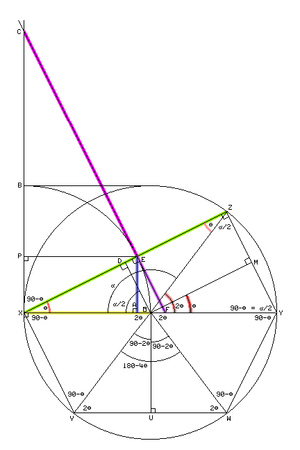
Input Values | ΔXEF (XE=1) | Angle | ΔXDO (XO=1) | Poincaré Sphere (r = 1) | Sphere Separation | Stylus Motion | |||||||||||||||
---|---|---|---|---|---|---|---|---|---|---|---|---|---|---|---|---|---|---|---|---|---|
Matrix used with |
% Blend | dB | tan(θ) FE opp |
sec(θ) XF hyp |
xsc(θ) OF hyp |
csc(θ) XC hyp |
xsc(θ) BC hyp |
∠EXF ZXY θ |
∠ZOY 2θ |
cos(θ) XD adj |
sin(θ) OD opp |
∠XOZ α | XZ Chord |
OD ⊥ XZ Chord |
OM ⊥ YZ Chord |
OU ⊥ VW Chord |
OD dB | OM dB |
OU dB |
to opp chan ∠PXE |
to adj chan ∠AXE |
Calc: | bl % | vdB | = bl | sec(θ) | XF-1 | csc(θ) | XC-1 | atn(FE) | 2θ | cos(θ) | sin(θ) | 180-2θ | 2sin(α/2) | cos(α/2) | cos(θ) | sin(2θ) | vdB | vdB | vdB | 90-θ | θ |
SQ-b,HA-b | 100.0 | 0.0 | 1.000 | 1.414 | 0.414 | 1.414 | 0.414 | 45.0 | 90.0 | 0.707 | 0.707 | 90.0 | 1.414 | 0.707 | 0.707 | 1.000 | -3.01 | -3.01 | 0.00 | 45.0 | 45.0 |
EV4-bd | 80.0 | -1.9 | 0.800 | 1.281 | 0.281 | 1.601 | 0.601 | 38.7 | 77.3 | 0.781 | 0.625 | 102.7 | 1.562 | 0.625 | 0.781 | 0.976 | -4.09 | -2.15 | -0.21 | 51.3 | 38.7 |
Nar | 67.0 | -3.5 | 0.670 | 1.204 | 0.204 | 1.797 | 0.797 | 33.8 | 67.6 | 0.831 | 0.557 | 112.4 | 1.662 | 0.557 | 0.831 | 0.925 | -5.09 | -1.61 | -0.68 | 56.2 | 33.8 |
Nar2 | 60.0 | -4.4 | 0.600 | 1.166 | 0.166 | 1.944 | 0.944 | 31.0 | 61.9 | 0.857 | 0.514 | 118.1 | 1.715 | 0.514 | 0.857 | 0.882 | -5.77 | -1.34 | -1.09 | 59.0 | 31.0 |
DQ-bd | 57.7 | -4.8 | 0.577 | 1.155 | 0.155 | 2.001 | 1.001 | 30.0 | 60.0 | 0.866 | 0.500 | 120.0 | 1.732 | 0.500 | 0.866 | 0.866 | -6.03 | -1.25 | -1.25 | 60.0 | 30.0 |
EV4-be,DQ-be | 50.0 | -6.0 | 0.500 | 1.118 | 0.118 | 2.236 | 1.236 | 26.6 | 53.1 | 0.894 | 0.447 | 126.9 | 1.789 | 0.447 | 0.894 | 0.800 | -6.99 | -0.97 | -1.94 | 63.4 | 26.6 |
QS,UM,H,HA-f | 41.4 | -7.7 | 0.414 | 1.082 | 0.082 | 2.614 | 1.614 | 22.5 | 45.0 | 0.924 | 0.383 | 135.0 | 1.848 | 0.383 | 0.924 | 0.707 | -8.35 | -0.69 | -3.01 | 67.5 | 22.5 |
SQB-bd,EVU-bd | 40.0 | -8.0 | 0.400 | 1.077 | 0.077 | 2.693 | 1.693 | 21.8 | 43.6 | 0.928 | 0.371 | 136.4 | 1.857 | 0.371 | 0.928 | 0.690 | -8.60 | -0.64 | -3.23 | 68.2 | 21.8 |
UQE | 31.8 | -10.0 | 0.318 | 1.049 | 0.049 | 3.300 | 2.300 | 17.6 | 35.3 | 0.953 | 0.303 | 144.7 | 1.906 | 0.303 | 0.953 | 0.578 | -10.4 | -0.42 | -4.77 | 72.4 | 17.6 |
EV4-fe | 30.0 | -10.5 | 0.300 | 1.044 | 0.044 | 3.480 | 2.480 | 16.7 | 33.4 | 0.958 | 0.287 | 146.6 | 1.916 | 0.287 | 0.958 | 0.550 | -10.8 | -0.37 | -5.19 | 73.3 | 16.7 |
DQ-fe | 25.0 | -12.0 | 0.250 | 1.031 | 0.031 | 4.123 | 3.123 | 14.0 | 28.1 | 0.970 | 0.243 | 151.9 | 1.940 | 0.243 | 0.970 | 0.471 | -12.3 | -0.26 | -6.55 | 76.0 | 14.0 |
EV4-fd,EVU-fd | 20.0 | -14.0 | 0.200 | 1.020 | 0.020 | 5.099 | 4.099 | 11.3 | 22.6 | 0.981 | 0.196 | 157.4 | 1.961 | 0.196 | 0.981 | 0.385 | -14.2 | -0.17 | -8.30 | 78.7 | 11.3 |
SQB-fd | 10.0 | -20.0 | 0.100 | 1.005 | 0.005 | 10.050 | 9.050 | 5.7 | 11.4 | 0.995 | 0.100 | 168.6 | 1.990 | 0.100 | 0.995 | 0.198 | -20.0 | -0.04 | -14.0 | 84.3 | 5.7 |
Wide | 5.0 | -26.0 | 0.050 | 1.001 | 0.001 | 20.025 | 19.025 | 2.9 | 5.7 | 0.999 | 0.050 | 174.3 | 1.998 | 0.050 | 0.999 | 0.100 | -26.0 | -0.01 | -20.0 | 87.1 | 2.9 |
DQ-fd | 0.0 | -80.0 | 0.000 | 1.000 | 0.000 | 99.000 | 98.001 | 0.0 | 0.0 | 1.000 | 0.000 | 180.0 | 2.000 | 0.000 | 1.000 | 0.000 | -80.0 | 0.00 | -80.0 | 90.0 | 0.0 |
Matrix | Blend | dB | FE | XF | OF | XC | BC | θ | 2θ | XD | OD | α | XZ | OD | OM | OU | OD dB | OM dB | OU dB | ∠PXE | ∠AXE |
Here are all of the items above put into one table.
The variables in the table are:
MATRIX COEFFICIENTS
USING ΔXEF
USING ΔCEX
USING ΔXDO and ΔXAE
TRIGONOMETRIC AND GEOMETRIC IDENTITIES
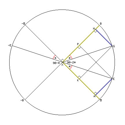
STYLUS VECTORS (Lower diagram for proper orientation to a record groove)
POINCARÉ SPHERE VALUES
SPHERE ANGLES
SPHERE ANGLE OPPOSITE
SPHERE ANGLE ADJACENT
SPHERE ANGLE CODED TO CODED
Hans Wallach, Edwin Newman, and Mark Rosenzweig defined the precedence effect in 1949. Helmut Haas later investigated the subject more in 1949.
They showed that when a sound reaches the ears, followed by an identical sound from a different direction, the listener hears only one sound where the first sound came from.
The delay between the sounds can be as long as:
- 5 ms for clicks (sound travels about 5.5 feet)
- 40 ms for complex sounds (speech or music - sound travels about 45 feet).
Larger delays are heard as echoes.
Human hearing uses these time and level differences in sounds reaching each ear to indicate the direction each sound comes from.
A special microphone array is used to create a surround field.
It encodes a quadraphonic matrix signal with the time delays already included to give additional clues to correctly locate the sound.
No separation enhancement is needed in playback.
Here is a table of the relative levels and delays (in microseconds) received on the input microphones l, r, and s of such a recording for different directions of sound sources:
Angle | Level l | Delay l |
Level r | Delay r |
Level s | Delay s |
Direction | 1st | 2nd | 3rd | |||||
0 | 0.866 | 0 | 0.866 | 0 | ~ 0.200 | 885 | Straight Ahead | l r | s | ||||||
30 | 0.707 | 369 | 0.966 | 0 | 0.259 | 951 | r | l | s | ||||||
60 | 0.500 | 639 | 1.000 | 0 | 0.500 | 762 | Right Mic | r | l s | ||||||
90 | 0.259 | 737 | 0.966 | 0 | 0.707 | 369 | Straight Right | r | s | l | |||||
120 | ~ 0.200 | 762 | 0.866 | 123 | 0.866 | 0 | r s | l | |||||||
180 | 0.500 | 885 | 0.500 | 885 | 1.000 | 0 | Straight Back Mic | s | l r | ||||||
240 | 0.866 | 123 | ~ 0.200 | 762 | 0.866 | 0 | l s | r | |||||||
270 | 0.966 | 0 | 0.259 | 737 | 0.707 | 369 | Straight Left | l | s | r | |||||
300 | 1.000 | 0 | 0.500 | 639 | 0.500 | 762 | Left Mic | l | r s | ||||||
330 | 0.966 | 0 | 0.707 | 369 | 0.259 | 951 | l | r | s | ||||||
360 | 0.866 | 0 | 0.866 | 0 | ~ 0.200 | 885 | Straight Ahead | l r | s |
~ Approximate value - Spill sound from room reflections into mics.
The stereo recording is matrixed from these three channels:
Decoding works with Dolby Surround or with any regular matrix (RM or QM) decoder.
Notice that this idea works only with a great-circle matrix. It won't work with phase matrix systems.
The separations in a quadraphonic program that the listener notices the most are:
The other separations are not as noticeable. The separation between left back and right back is usually the least noticed.
(This occurs on the right side too.)
Normal level-differential panning techniques cannot produce an audible image between these
speakers
unless the listener turns his head so that one each ear is facing each speaker.
But there are several ways to make the side image appear, and some of them use normal
panning techniques when the recording is mixed:
Any surround sound system with speakers located directly to the left and directly to the right of the listener does not have the side-location problem.
- The Dynaco Diamond has these speakers and unintentionally fixed this problem.
- The Denon QX Dual Triphonic system also unintentionally fixed this problem.
This method uses the precedence effect to make the separations seem larger.
It introduced a phase-reversed and delayed version of each decoded channel into the
diagonally opposite channel.
- It did increase the apparent separation.
- It fixed the side location problem.
- It also caused an annoying tension feeling from phase reversed sound.
This uses microphones spaced the same distance apart that human ears are spaced. The microphones are aimed to the sides.
The listener listens to a recording from those microphones through earphones.
The effect is very real, but there is no sound from the front or the back even if such sounds were there.
The effect is also audible with speakers.
Quadraphonic speakers using an RM or QM matrix will place the images between the side speakers with the listener's head facing the front.
This places images between the speakers, but does not produce a quadraphonic recording.
Dolby Surround plays a normally matrixed Dolby Surround, RM, or QM recording, decoding the dialog, left, right, and surround channels.
The surround channels are delayed by the decoder to prevent surround leakage into the front from being noticed.
But this delay also uses the precedence effect to cause the side images to be located by the listener correctly as it was panned.
- It requires the listener to continue facing forward to hear all of the location effects correctly.
This method uses the precedence effect to make the separations seem larger.
The difference is that it is in the recording. Nothing is added to the decoding equipment.
This is a surround (or Spheround) version of binaural recording.
It has delays in both left-right and front-back directions (and up-down directions too for Spheround).
So the position of the listener's head is unimportant.
- A special microphone technique creates a sound field. The human hearing system does the rest.
- This is like binaural recording, but works in a plane or even a solid space.
- It increases the apparent separation.
- No other separation enhancement is needed.
- It fixes the side-location problem.
- It gives a natural "you are there" effect that is a characteristic of sound fields.
The effect here is having so many channels that at least one or two pairs of channels are at opposite sides of the listener's head. This removes the side-location problem.
The Octophonic system works well.
This method uses the precedence effect to make the separations seem larger.
It introduces a delayed version of each decoded channel into the diagonally opposite channel or to other speakers nearby but farther away.
The phase is not reversed as it is in the Diagonal Delays above.
- It does increase the apparent separation.
- It fixes the side location problem.
- It does not cause the annoying tension feeling from phase reversed sound.
- These speakers do not have to be exactly diagonally opposite. They just need to be heard by the opposite ear.
There are several different methods:
In this method, the gain of each channel is quickly varied to make the dominant channels
louder and the other channels quieter.
This seemed to make the separation larger, but it had two disadvantages:
- It reduced the level of any ambience in the recording.
- It had the effect of "pumping" (where changes in signal levels or ambience caused by gain changes are noticed by the listener).
This method uses the precedence effect to make the separations seem larger.
It introduced a phase-reversed and delayed version of each decoded channel into the
diagonally opposite channel.
- It did increase the apparent separation.
- It fixed the side location problem.
- It also caused an annoying tension feeling from phase reversed sound.
This method is used in the Sansui Variomatrix, the CBS Variblend, Dolby Pro-Logic, the Electro-Voice separation enhancement, and UniQuad Autovary.
- This looks for where the strongest signal is and momentarily adjusts the matrix to increase separation for that signal.
- The reduced separations for the other channels are not normally noticed.
- The upper diagram shows the normal separation pattern for Dolby Surround.
- The lower diagram shows the instantaneous changes Dolby Surround makes with a dominant front-center soloist.
- Decoding moves away from dominant sources. Front separation widens while back separation narrows with front-center solos.
DECODE EQUATIONS | DECODE RESULTS | Image | |||
---|---|---|---|---|---|
Without Pro-Logic | |||||
Left_Speaker | = 1.00 Left_Matrix | Left_Speaker | = 1.00 Left + .707 Dialog + .707 j Surround | ||
Right_Speaker | = 1.00 Right_Matrix | Right_Speaker | = 1.00 Right + .707 Dialog - .707 j Surround | ||
Dialog_Speaker | = .707 Left_Matrix + .707 Right_Matrix | Dialog_Speaker | = 1.00 Dialog + .707 Left + .707 Right | ||
Surround_Speaker | = .707 Right_Matrix - .707 Left_Matrix | Surround_Speaker | = 1.00 Surround + .707 Left - .707 Right | ||
With Pro-Logic (front solo) | |||||
Left_Speaker | = .924 Left_Matrix - .383 Right_Matrix | Left_Speaker | = .924 Left + .383 Dialog + .924 j Surround | ||
Right_Speaker | = .924 Right_Matrix - .383 Left_Matrix | Right_Speaker | = .924 Right + .383 Dialog - .924 j Surround | ||
Dialog_Speaker | = .707 Left_Matrix + .707 Right_Matrix | Dialog_Speaker | = 1.00 Dialog + .707 Left + .707 Right | ||
Surround_Speaker | = .707 Right_Matrix - .707 Left_Matrix | Surround_Speaker | = 1.00 Surround - .707 Left - .707 Right |
Pumping is inaudible using this method because the signal levels are unchanged.
Only the instantaneously perceived directions of the low level signals are changed.
These are not normally noticed because human hearing normally notices the direction
of the dominant signal over the other signals.
Dolby Surround plays a normally matrixed Dolby Surround, RM, or QM recording, decoding the dialog, left, right, and surround channels.
The surround channels are delayed by the decoder.
This delay prevents surround leakage into the front from being noticed.
This delay prevents front leakage into the surround channels from being noticed.
This delay also uses the precedence effect to cause the side images to be located correctly as panned by the listener.
- It requires the listener to continue facing forward to hear all of the location effects correctly.
This method uses the precedence effect to make the separations seem larger. The difference is that it is in the recording. Nothing is added to the decoding equipment.
See "Theorem 7: Surround Fields" above and the Surround Fields page.
- A special microphone technique creates a sound field. The human hearing system does the rest.
- It increases the apparent separation.
- No other separation enhancement is needed.
- It fixes the side-location problem.
- It gives a natural "you are there" effect that is a characteristic of sound fields.
Each sound comes from a wall of sound, not a single point. This does the following:
- It makes it useful from more locations in the room.
- It creates a linear wave front instead of multiple spherical wave fronts.
- It keeps the ears from finding a single speaker in the room.
Thus, the ears locate the correct direction of the sound as panned.
This method uses the precedence effect to make the separations seem larger.
It introduces a delayed version of each decoded channel into the diagonally opposite channel or to other speakers nearby but farther away.
The phase is not reversed as it is in the Diagonal Delays above.
- It does increase the apparent separation.
- It fixes the side location problem.
- It does not cause the annoying tension feeling from phase reversed sound.
- These speakers do not have to be exactly diagonally opposite. They just need to be heard by the opposite ear.
This procedure was developed by the page author through empirical experimentation. But it seems to work very well:
The page author wanted to create a diagram of room size as shown in Leonard Feldman's book "Four Channel Sound" on page 62.
 :
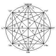
Diagram calculations
Value A | Separation between front channels |
Value B | Separation between back channels |
Value C | Separation between front and back channels on each side |
Value D | Separation between each front channel and the opposite stereo channel |
Value E | Separation between each back channel and the opposite stereo channel |
Value F | Separation between each back channel and a mono signal |
Value G | Separation between the center back signal and a mono signal |
Value H | Separation between each front channel and the center back channel |
Value K | Separation between each front channel and the opposite back channel |
Value S | Normal stereo separation of the record (assumed 40 dB) |
Value T | Separation between a stereo channel and mono (3 dB) |
Value U | Separation between a stereo channel and the center back signal |
For values of 0 dB, he had to use 0.05 dB to keep Excel from giving an error.
He took the common logarithm of each of the dB values above.
This gave a scale of values from -1.3 to 1.6 for values from .05 dB to 40 dB.
He then centered the values by subtracting 0.5 from each value for the final effect.
This gave a scale of values from -1.8 to 1.1 for values from .05 dB to 40 dB.
This would expand the space for large separations while contracting it for small ones. It also gave the wanted appearance.
Matrix | A | B | C | D | E | F | G | H | K | S | T | U |
---|---|---|---|---|---|---|---|---|---|---|---|---|
QS | 3 | 3 | 3 | 8.3 | 8.3 | 8.3 | 40 | 8.3 | 40 | 40 | 3 | 3 |
-0.02 | -0.02 | -0.02 | 0.42 | 0.42 | 0.42 | 1.10 | 0.42 | 1.10 | 1.10 | -0.02 | -0.02 | |
EV4 | 8.3 | 0.2 | 4.9 | 14 | 4.1 | 19 | 40 | 5.1 | 5.3 | 40 | 3 | 3 |
0.42 | -1.2 | 0.19 | 0.65 | 0.11 | 0.78 | 1.10 | 0.21 | 0.22 | 1.10 | -0.02 | -0.02 |
This frame is a 4-unit by 4-unit square centered on the origin of the graph.
This plot area is an 8-unit by 8-unit box centered on the origin of the graph.
W is the width at the front. Y is the width at the back.
X is the depth at the front. Z is the depth at the back.
LOCATION | DIRECTION | SAME SIDE | LET | OPP INPUT | LET | DIAGONAL | LET | MIRROR | OFFSET | FORMULA |
---|---|---|---|---|---|---|---|---|---|---|
COEFFICIENTS: | 1.0 | 0.1 | 0.01 | +2 | ||||||
Right Front | Horizontal | Left Front | A | Left Input | D | Left Back | K | Left Front | +2 | 'W = 1.0 A + 0.1 D + 0.01 K + 2 |
Left Front | Horizontal | Right Front | A | Right Input | D | Right Back | K | Right Front | +2 | '-W = -1.0 A - 0.1 D - 0.01 K - 2 |
Right Front | Vertical | Right Back | C | Center Back | H | Left Back | K | Left Front | +2 | 'X = 1.0 C + 0.1 H + 0.01 K + 2 |
Left Front | Vertical | Left Back | C | Center Back | H | Right Back | K | Right Front | +2 | 'X = 1.0 C + 0.1 H + 0.01 K + 2 |
Right Back | Horizontal | Left Back | B | Left Input | E | Left Front | K | Left Back | +2 | 'Y = 1.0 B + 0.1 E + 0.01 K + 2 |
Left Back | Horizontal | Right Back | B | Right Input | E | Right Front | K | Right Back | +2 | '-Y = -1.0 B - 0.1 E - 0.01 K - 2 |
Right Back | Vertical | Right Front | C | Mono | F | Left Front | K | Left Back | +2 | 'Z = -1.0 C - 0.1 F - 0.01 K - 2 |
Left Back | Vertical | Left Front | C | Mono | F | Right Front | K | Right Back | +2 | 'Z = -1.0 C - 0.1 F - 0.01 K - 2 |
A second set was needed for diamond speaker layouts:
LOCATION | DIRECTION | SAME SIDE | LET | OPP INPUT | LET | DIAGONAL | LET | MIRROR | OFFSET | FORMULA |
---|---|---|---|---|---|---|---|---|---|---|
COEFFICIENTS: | 1.0 | 0.1 | 0.1 | +2 | ||||||
Front | Horizontal | 0 | 'W = 0 | |||||||
Back | Horizontal | 0 | 'W = 0 | |||||||
Front | Vertical | Back | G | Left Input | T | Right Input | T | Back | +2 | 'X = 1.0 G + 0.1 T + 0.1 T + 2 |
Back | Vertical | Front | G | Left Input | U | Right Input | U | Front | +2 | '-X = -1.0 G - 0.1 U - 0.1 U - 2 |
Right | Horizontal | Left | S | Mono | T | Back | U | Left | +2 | 'Y = 1.0 S + 0.1 T + 0.1 U + 2 |
Left | Horizontal | Right | S | Mono | T | Back | U | Right | +2 | '-Y = -1.0 S - 0.1 T - 0.1 U - 2 |
Right | Vertical | 0 | 'Z = 0 | |||||||
Left | Vertical | 0 | 'Z = 0 |
Provide a table row for the x coordinates and a row for the y coordinates
The points are in the order lb, lf, rf, rb, lb (for diamond pattern: l, f, r, b, l).
The lb point is repeated to complete the quadrilateral (repeat l for the diamond pattern).
Use the plot option: Scatter with straight lines.
Select the orange values to make the QS plot.
EFFECT VALUES | VALUES | lb | lf | rf | rb | lb | IMAGE | |||||||||||||||
---|---|---|---|---|---|---|---|---|---|---|---|---|---|---|---|---|---|---|---|---|---|---|
Matrix | A | B | C | D | E | F | G | H | K | S | T | U | W | Y | x | -Y | -W | +W | +Y | -Y | ||
X | Z | y | Z | X | X | Z | Z | |||||||||||||||
QS | 3 | 3 | 3 | 8.3 | 8.3 | 8.3 | 40 | 8.3 | 40 | 40 | 3 | 3 | 2.03 | 2.03 | x | -2.03 | -2.03 | 2.03 |
2.03 | -2.03 |
||
effect | -0.02 | -0.02 | -0.02 | 0.42 | 0.42 | 0.42 | 1.10 | 0.42 | 1.10 | 1.10 | -0.02 | -0.02 | 2.03 | -2.03 | y | -2.03 | 2.03 | 2.03 |
-2.03 | -2.03 |
||
EV4 | 8.3 | 0.2 | 4.9 | 14 | 4.1 | 19 | 40 | 5.1 | 5.3 | 40 | 3 | 3 | 2.49 | 0.81 | x | -0.81 | -2.49 | 2.49 | 0.81 | -0.81 | ||
effect | 0.42 | -1.2 | 0.19 | 0.65 | 0.11 | 0.78 | 1.10 | 0.21 | 0.22 | 1.10 | -0.02 | -0.02 | 2.21 | -2.27 | y | -2.27 | 2.21 | 2.21 | -2.27 | -2.27 | ||
EFFECT VALUES | VALUES | l | f | r | b | l | IMAGE | |||||||||||||||
Matrix | A | B | C | D | E | F | G | H | K | S | T | U | W | Y | x | -Y | -W | +Y | +W | -Y | ||
X | Z | y | -Z | +X | +Z | -X | -Z | |||||||||||||||
DD | 3 | 3 | 3 | 8.3 | 8.3 | 8.3 | 40 | 8.3 | 40 | 40 | 3 | 3 | 0 | 3.10 | x | -3.10 | 0 | 3.10 | 0 | -3.10 | ||
effect | -0.02 | -0.02 | -0.02 | 0.42 | 0.42 | 0.42 | 1.10 | 0.42 | 1.10 | 1.10 | -0.02 | -0.02 | 3.10 | 0 | y | 0 | 3.10 | 0 | -3.10 | 0 |