 The following page shows the proof:
Many circuits exist for switching between series and parallel operation. But the selection of a particular switching circuit depends on what kinds of devices are being switched and the various constraints imposed by each kind of device.
Here is a list of the various kinds of devices commonly switched, and the constraints each kind imposes on the design:
So any switching circuit of this type must be designed for the actual use intended.
The formulas for calculation of the parameters of series and parallel circuits can be found here:
Calculation of series and parallel circuit parameters
The following page compares the various circuits for series/parallel switching:
Comparing series/parallel circuits
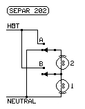
The following page shows the proof:
Proof that all-combinations switching can't be polarity-safe or neutral-safe
The extra mark by each lamp (in the form of a short arc) in these diagrams indicates the lead that should be connected to the screw shell of the lamp (image at right):
In the diagrams offered as proof, the extra marks are not used to show that polarity-safe and neutral-safe are impossible.
The following page shows the design principles:
Designing series-parallel switching
The circuits described here are simple circuits that can be used for low voltage circuits. They were also used for photoflood lighting circuits before the necessity was known of having the screw shell of a line-voltage operated lamp on the neutral side (for safety if bulb is removed). The requirement of polarized plugs with the screw shell connected to the neutral blade makes these circuits (except SEPAR 204) not code compliant today for line-voltage circuits.
The SEPAR circuit numbers used here have been used by the page author for years to catalog the various circuits.
Here are the constraints incandescent loads impose on the design:
The following variations are permitted when low voltage lamps are used in series-parallel switching circuits.
The same circuits can be used for switching resistances, impedances and, nonpolarized heating elements.
There are no constraints on circuits used to switch resistances and impedances other than those demanded by the circuit used and the circuit it is used in. But the following cautions must be observed with these circuits.
SIMPLE CIRCUITS SELECTING SERIES OR PARALLEL OPERATION OF LAMPS AND IMPEDANCES
The circuits described here are advanced circuits that can be used for line voltage circuits. They can be used for photoflood lighting circuits, conforming to the necessity of having the screw shell of a line-voltage operated lamp on the neutral side (for safety if bulb is removed).
The SEPAR circuit numbers used here have been used by the page author for years to catalog the various circuits.
The SP-STD circuit numbers are new designations by the page author for new circuits.
Here are the constraints line voltage loads impose on the design:
The following variations are permitted when line voltage lamps are used in series-parallel switching circuits.
The same circuits can be used for switching impedances and heating elements.
These are the constraints on circuits used to switch resistances, impedances, and heaters:
LINE VOLTAGE CIRCUITS SELECTING SERIES OR PARALLEL OPERATION OF LAMPS AND IMPEDANCES
The circuits described here are circuits that can be used for switching batteries to change voltage and ampere hour capacities. They can be used for changing the configuration for charging and for using the batteries. Most of them are simple circuits.
The SP-STD circuit numbers are new designations by the page author for new circuits.
Here are the constraints batteries impose on the design:
The following variations are permitted when batteries are used in series-parallel switching circuits.
CIRCUITS SELECTING SERIES OR PARALLEL OPERATION OF BATTERIES
The circuits described here are circuits that can be used for switching guitar pickups to change the sound of the guitar.
The SP-STD circuit numbers are new designations by the page author for new circuits.
Here are the constraints guitar pickups impose on the design:
The following variations are permitted when guitar pickups lamps are used in series-parallel switching circuits.
The same circuits can be used for switching impedances and nonpolarized heating elements.
CIRCUITS SELECTING SERIES OR PARALLEL OPERATION OF GUITAR PICKUPS
The circuits described here are circuits that can be used for switching speakers to change the number of speakers while keeping the impedance presented to the amp near a set impedance.
Here are the constraints this kind of load imposes on the design:
The following variations are permitted when speakers are used in series-parallel switching circuits.
The same circuits can be used for switching impedances and nonpolarized heating elements.
CIRCUITS SELECTING SERIES OR PARALLEL OPERATION OF SPEAKERS
LINKS: