CIRCUITS FOR SELECTING
BETWEEN SERIES OR PARALLEL OPERATION
OF BATTERIES

Simple Battery Circuits

The following circuits are circuits that can be used for batteries. Operation of batteries in series and parallel switching has different purposes than those for switching loads. The purposes are:

  1. Draining batteries in series, while charging them in parallel to keep one battery from becoming reverse charged in the series when the others are still discharging.
  2. Changing the voltage and ampere-hour ratings of the batteries for different applications.

Here is a list of the constraints batteries impose on the design:

The SEPAR circuit numbers used here have been used by the page author for years to catalog the various circuits.

The SP-STD circuit numbers are new designations by the page author for new circuits.

The following variations are permitted when batteries are used in series-parallel switching circuits.

Note that, to conserve website server storage space and bandwidth, some of the following diagrams show light bulbs instead of batteries because they are the same diagrams used on the lightbulb pages. Let the end of the light bulb with the extra arc showing the screw shell be the negative terminal of the battery.

Examples:

  • The Original Series-Parallel Switchbox for Two Batteries.
    SEPAR 201

    This has been used for batteries for a very long time.

    The switch is set to the "dim" position to use the batteries at twice the battery voltage, and to the "ON" position to use the batteries at twice the ampere-hour rating at the battery voltage, or to charge rechargeable batteries.

    There is no center off position in this version.

    Remember that batteries are substituted for the lamps shown in the diagrams. Let the end of the light bulb with the extra arc showing the screw shell be the negative terminal of the battery.

    The switches are labeled DIM and ON to save server storage space and bandwidth by reusing a diagram intended for lamps. Relabel them with the related output voltages.

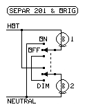
  • SEPAR 201 (a modification of the Original Series-Parallel Switchbox)

    This is a modification of the above circuit, adding a center position on the switch to turn the battery circuit off.

    The switch is set to the "DIM" position to use the batteries at twice the battery voltage, and to the "ON" position to use the batteries at twice the ampere-hour rating at the battery voltage, or to charge rechargeable batteries.

    Remember that batteries are substituted for the lamps shown in the diagrams. Let the end of the light bulb with the extra arc showing the screw shell be the negative terminal of the battery.

    The switches are labeled DIM and ON to save server storage space and bandwidth by reusing a diagram. Relabel them with the related output voltages.

KEY TO TABLE ENTRIES

ON
  - Connected directly to output
     (label this switch position with
     the battery voltage)

DIM
  - In series with other batteries
     (label this switch position with
     the multiple of the battery
     voltage produced)

SER
  - In series with other batteries

CHG
  - Position for charging batteries

off
  - One or both ends of the
     battery are disconnected


  - Switch position unimportant

V
  - Output Voltage as a multiple
     of each battery's voltage

A Hr
  - Output Ampere Hours as a
     multiple of each battery's
     Ampere Hour rating

Letters indicate closed switches.

No letter for a switch, or an o for a switch, means the switch is open, or is in the unlabeled position.

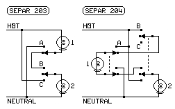
  • SEPAR 203 and SEPAR 204

    SEPAR 203
    SWITCHBATTERYOUTPUT
    AB C12VA Hr
    oooffoff00
    oBSERSER2 ×1 ×
    oCoffON1 ×1 ×
    AoONoff1 ×1 ×
    ABONoff1 ×1 ×
    ACONON1 ×2 ×

    This Series-Parallel Switching Circuit can use either battery alone, both in series, or both in parallel.

    A later version of this series-parallel switching circuit is (SEPAR 204). The switch positions are exactly the same, but the positive connections are removed if the negative side is opened.

    Note that any switch position with a letter on it is the position indicated by that letter in the table.

    Remember that batteries are substituted for the lamps shown in the diagrams.

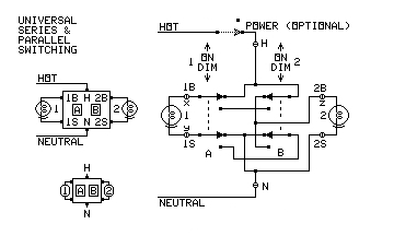
  • SP-STD 2 (Built by page author in 2013)

    SP-STD 2
    SWITCHBATTERYOUTPUT
    AB12VA Hr
    DIMDIMSERSER2 ×1 ×
    DIMONoffON1 ×1 ×
    ONDIMONoff1 ×1 ×
    ONONONON1 ×2 ×
    ONONCHGCHG1 ×2 ×

    This circuit provides all possible combinations except all off.

    This circuit never removes the negative connection from a battery except when the battery is in series, or momentarily while a switch is being thrown. Remember that batteries are substituted for the lamps shown in the diagrams. The mark under each "lamp" in the diagram indicates the negative terminal of the battery.

    Note that no OFF position is available. If an off position is needed, an optional POWER switch can be connected in the positive line as shown.

    It is best for the batteries to be charged in the ON position (when they are in parallel).

    The switch should be labeled with the battery voltage for ON, and twice the battery voltage for DIM.

    Cascading SP-STD 2 units can place different voltages in parallel (causing battery damage) with some switch settings, so it is not recommended.

  • SP-BAT 3

    SP-BAT 3
    SWITCH
    BATTERIES OUTPUT
     
    123VA Hr
    SER
    SERSERSER3 ×1 ×
    PAR
    ONONON1 ×3 ×
    PAR
    CHGCHGCHG1 ×3 ×

    This is SP-BAT 3. Al four switches are ganged together as one four-pole switch.

    It is best for the batteries to be charged in the PAR position (when they are in parallel).

    Note that no OFF position is available. If an off position is needed, an optional POWER switch can be connected in the positive line.

    The switch should be labeled with the battery voltage for PAR, and three times the battery voltage for SER.

    This can be reduced to two batteries, or to any number of batteries.

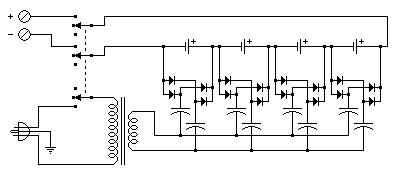
  • SP-BAT

    SP-BAT

    This is a circuit that places the batteries in series to add their voltages, but effectively places them in parallel during the charging process. The switch selects using the batteries, charging the batteries, and off.

    The capacitors isolate the paralleled capacitor/rectifier networks from each other. The rated voltages of the capacitors and rectifiers must be four times the total battery voltage (all cells in series). The capacitors are nonpolarized, with values adjusted to charge the batteries at the recommended rate.

    This will work with any number of batteries. This example shows four.


LINKS:

  1. SELECTING SERIES OR PARALLEL OPERATION (Main Page)
  2. LIGHT BULBS, SPECTRA, and HUMAN VISION
  3. Computers, Science, and Measurement