| SIMPLE SWITCHING |
-
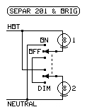
The Original Photoflood Series-Parallel Switchbox for Two Lamps.
This has been used for high-color-temperature short-life photoflood lamps to conserve the
lives of these bulbs since the 1930s. The lamps are dimmed while the photographer is setting up
the shot.
The switch is set to the dim position while the photographer sets up the shot, and the
bright position during the actual photography. There is no center off position in this
version.
2 switch settings.
- SEPAR 201 (a modification of the Original Photoflood Series-Parallel Switchbox)
This is a modification of the above circuit, adding a center position on the switch to turn
the lights off.
The switch is set to the dim position while the photographer sets up the shot, and the
bright position during the actual photography. The center position turns off the lights.
3 switch settings, all unique & useful.
|
|
|
|
|
|
|
|
|
|
|
|
|
|
|
-
SEPAR 401
| SWITCH | LAMPS |
|
SWITCH | LAMPS |
| Settings | 1 | 2 | 3 | 4 |
Settings | 1 | 2 | 3 | 4 |
| o † | off | off | off | off |
ACGJ † | DIM | DIM | off | off |
| AB | ON | off | off | off |
AEJ | DIM | off | DIM | off |
| BCF | off | ON | off | off |
AHL | DIM | off | off | DIM |
| DFJ | off | off | ON | off |
CEFJ | off | DIM | DIM | off |
| JK | off | off | off | ON |
CFHL | off | DIM | off | DIM |
| ABCF † | ON | ON | off | off |
DFL | off | off | DIM | DIM |
| ABDFJ | ON | off | ON | off |
ACDJ † | DIM | DIM | DIM | off |
| ABJK | ON | off | off | ON |
ACGL | DIM | DIM | off | DIM |
| BCDFJ | off | ON | ON | off |
AEL | DIM | off | DIM | DIM |
| BCFJK | off | ON | off | ON |
BCDK | off | DIM | DIM | DIM |
| DFJK | off | off | ON | ON |
ACDL † | Glim | Glim | Glim | Glim |
| ABCDFJ † | ON | ON | ON | off |
(P-S) | - | - | - | - |
| ABCFJK | ON | ON | off | ON |
ACGJK | DIM | DIM | off | ON |
| ABDFJK | ON | off | ON | ON |
AEJK | DIM | off | DIM | ON |
| BCDFJK | off | ON | ON | ON |
ABCGK | ON | DIM | off | DIM |
| ABCDFJK † | ON | ON | ON | ON |
ABEK | ON | off | DIM | DIM |
| (S-P) | - | - | - | - |
BCDFL | off | ON | DIM | DIM |
| ACEGJ | DIM | Glim | Glim | off |
CEFJK | off | DIM | DIM | ON |
| ACEFJ | Glim | Glim | DIM | off |
ABCDFL | ON | ON | DIM | DIM |
| ACFHL | Glim | Glim | off | DIM |
ACDJK | DIM | DIM | DIM | ON |
| ADFHL | Glim | off | Glim | DIM |
ABCDK | ON | DIM | DIM | DIM |
| CDFHL | off | Glim | Glim | DIM |
(P-S-P) | - | - | - | - |
| ACEFL | Glim | Glim | DIM | DIM |
ACEFJK | Glim | Glim | DIM | ON |
| ACEGL | DIM | Glim | Glim | DIM |
ACEGJK | DIM | Glim | Glim | ON |
| ACDFHL | Glim | Glim | Glim | DIM |
ABCEGK | ON | Glim | Glim | DIM |
|
|
|
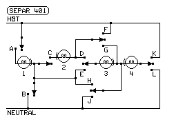
The page author got a plywood board with this circuit on it, made with knife
switches and sockets, at a school surplus-materials auction.
It provides all series combinations and all parallel combinations.
All 47 possible output displays shown, out of 648 switch settings.*
|
|
KEY TO TABLE ENTRIES
ON
- Connected directly to power
DIM
- 2 or 3 lamps in series
- series in a series-parallel
Glim
- 4 or more lamps in series
- parallel in a series-parallel
off
- No current through lamp
−
- Switch position unimportant
*
- All possible displays shown.
- Redundant combos not shown.
†
- Former settings for photofloods
Letters indicate closed switches.
No letter for a switch, or an o for a switch, means the switch is open, or is in the
unlabeled position.
|
|
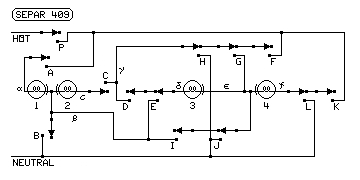
- SEPAR 409 (a modification of SEPAR 401)
This is a modification of the above circuit, adding an extra switch and using all
two-position switches.
See the details on the SEPAR 409 page
This is much more useful than SEPAR 401, providing two series of two lamps each.
864 connected switch settings, 56 unique & useful, out of 4096 total.
(3232 settings have multiple letter positions set in the same switch ladder.)
One more position for safe bulb changing.
|
|
|
| REGULAR SWITCHING MATRIX |
-
SEPAR 300 (The First Polarized Series-Parallel Switchbox for Three Lamps)
It was the first design where the switch positions were intuitive. The user could
set the switches for the desired combination of series and parallel.
For example, to connect lamps 1 and 2 in series:
- Set lamp 1 to FST (first).
- Set lamp 1 to the 1> (to) position.
- Set lamp 2 to >1 (from 1).
- Set lamp 2 to LST (last).
- Set lamp 3 to o (off).
It can leave a lamp connected to the hot side with no neutral connection, so
the circuit cannot be used with line-voltage lamps.
Almost all combinations are possible.
- SEPAR 400 (A Four-Lamp Version of SEPAR 300)
This system is expandable to SEPAR n00 for n lamps by adding these for each additional
lamp:
- Another column of the switches and its lamp
- Another position on each rotary switch
- Another horizontal bus wire
|
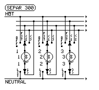
512 settings
Some are redundant.
|
|
-
SEPAR 330 (Advanced Polarized Series-Parallel Switchbox for Three Lamps)
The switch positions were intuitive. The user could set the switches for the desired
combination of series and parallel by looking at the labels.
For example, to connect lamps 1 and 2 in series:
- Set lamp 1 to FST (first) by not selecting any < (from) positions.
- Set lamp 1 to the 1> (to) position.
- Set lamp 2 to <1 (from 1).
- Other lamp 2 switches must not be set to a < position.
- Set lamp 2 to LST (last).
- Set lamp 3 to o (off).
It can leave a lamp connected to the hot side with no neutral connection, so
the circuit cannot be used with line-voltage lamps.
All combinations are possible.
- SEPAR 440 (A Four-Lamp Version of SEPAR 330)
This system is expandable to SEPAR nn0 for n lamps by adding these for each additional
lamp:
- Another column of the switches and its lamp
- Another double-pole double-throw switch to each column
- Another horizontal bus wire
|
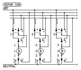
1728 settings
Some are redundant.
|
|
-
SEPAR 333 (Attempt to make a neutral-safe Series-Parallel Switchbox for Three
Lamps)
This is basically the SEPAR 330 with extra poles on the switches to disconnect the live
phase if no current path to the neutral from the live phase exists. The problem is that
it is easy to fool the circuit into allowing a connection to hot without a current path.
It is also possible to reverse the polarity of a lamp. Since it has no advantage over
SEPAR 330, it is not shown.
Epilog: The page author has since proved
that it is impossible to make a switching circuit that can provide all possible
combinations of series and parallel and that is also polarity-safe (never reverses
lamp polarity) and neutral-safe (never connects lamp to hot without a path to a
neutral connection).
- SEPAR 444 (A Four-Lamp Version of SEPAR 333)
This is not shown for the same reason. It was a dead-end project.
- SEPAR nnn, n000, nnnn, and nnn9 (replace n with the number of lamps) were more
interlocked versions of SEPAR 333 and 444). They were also dead-end projects for the
same reason.
|
|
| INFINITE SWITCHING MATRIX |
- SEPAR I-4 (an infinitely selectable system)
This is a system designed so that each end of each lamp can be connected to whatever
it needs to be connected to. It uses only two-position switches.
This can connect the lamps or devices in any possible network with any polarity.
Number of lamps: 4
Number of interconnection buses: 3
Number of rows of switches: 5
Number of columns of switches: 8
Number of switches: 40
Number of nonequivalent combinations: 1679616
- SEPAR I-n (an infinitely selectable system - replace n with number of lamps)
This is the same as SEPAR I-4, but is expandable for any number of lamps.
This can connect the lamps or devices in any possible network with any polarity.
The extra rows and pairs of columns are added at the dashed ends.
To add a lamp, add:
- one lamp with its two switch columns
- one switch row and bus
The extra rows are lettered in reverse alphabetical order.
Number of lamps: n
Number of interconnection buses: n-1
Number of rows of switches: n+1
Number of columns of switches: 2n
Number of switches: 2n (n+1) or 2n^2 + 2n
Number of nonequivalent combinations: (n+2) ^ 2n
Note that each column of n+1 two-position switches can be replaced with
a single rotary switch with n+2 positions. This is SEPAR I-nZ.
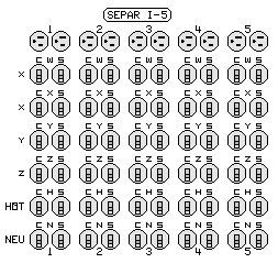
The panel at right is a SEPAR I-5.
|
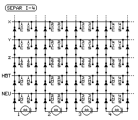
390625 nonequivalent settings
Some are redundant.
C = center contact
S = screw shell
|
|
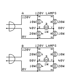 Using SEPAR I-5 infinitely selectable system for the proof circuit
This is the proof that a switching circuit with all
possibilities can't be polarity safe or neutral safe.
The following switches are turned on (to the named positions).
1HC - Lamp 1 center terminal is set to Hot
1ZS - Lamp 1 screw shell is set to bus Z
2HC - Lamp 2 center terminal is set to Hot
2YS - Lamp 2 screw shell is set to bus Y
3ZC - Lamp 3 center terminal is set to bus Z
3YS - Lamp 3 screw shell is set to bus Y
4ZC - Lamp 4 center terminal is set to bus Z
4NS - Lamp 4 screw shell is set to Neutral
5YC - Lamp 5 center terminal is set to bus Y
5NS - Lamp 5 screw shell is set to Neutral
|
|
|