SPEAKER CIRCUITS FOR SELECTING
BETWEEN SERIES OR PARALLEL OPERATION
TO MAINTAIN LOAD IMPEDANCE

Speaker Circuits

The following circuits are designed so that adding and removing speakers keeps the load on the amplifier at nearly the same impedance.

These circuits make no sense for any of the other items switched between series and parallel on these pages.

Here is a list of the constraints speakers impose on the design:

The SEPAR circuit numbers used here have been used by the page author for years to catalog the various circuits.

The SP-STD circuit numbers are new designations by the page author for new circuits.

The following variations are permitted when speakers are used in series-parallel switching circuits.

  • SP-SPK 4

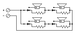
    SP-SPK 4

    This Series-Parallel Switching Circuit always uses the same parallel-series arrangement, but substitutes a resistor for any speaker that is turned off. Each switch turns the speaker connected to it on and off.

    The impedance the amplifier is expecting, the impedance of each speaker, and the resistance of each resistor should all be the same value. Each resistor must be able to take the full output power of the amp.

    Passive surround sound adaptors cannot be used with this circuit.

  • SPK-ROT Rotary Switch Systems.

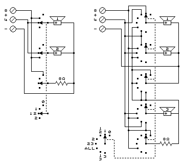
    SPK ROT SETS

    These circuits use ganged rotary switches to select the speakers in use and the proper impedance loading to the amp.

    The circuit on the left uses the 8Ω and 4Ω taps on the amplifier transformer to provide the proper impedance for two 8Ω speakers. Two speakers are placed in parallel and connected to the 4Ω output of the amp. An 8Ω resistor loads the amp when the speakers are turned off for headphone use.

    The circuit on the right uses the 8Ω and 4Ω taps on the amplifier transformer to provide the proper impedance for three 8Ω speakers. Any set of two speakers is placed in parallel and connected to the 4Ω output of the amp. When all three speakers are used, the speakers are placed in series-parallel, with an 8Ω resistor used to make the impedance correct for the 8Ω tap. The same 8Ω resistor loads the amp when the speakers are turned off for headphone use.

    These circuits were used mainly in the 1940s, 1950s, and 1960s when tube amplifiers were in general use. The advent of low output impedance transistor amplifiers means that amps are much less load-sensitive. But the minimum impedance the amplifier needs must not be violated, or the amp may destroy its output transistors.

    One difficulty of trying to build these circuits is finding the ganged rotary switches. Most manufacturers no longer make them.

    Passive surround sound adaptors cannot be used with these circuits.

  • SPK-70V Higher Voltage Line

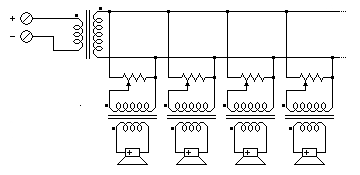
    SPK 70V

    This very successful alternative to series-parallel operation of multiple speakers is usually one of several related systems, based on the voltage on the distribution line.

    This uses the same principle that high voltage power transmission uses. Individual loads do not significantly load down the distribution line. The result is that much longer wiring runs are possible without the resistance of the wire being a factor.

    The output of the amplifier is boosted by a transformer to a higher voltage for the distribution line. Several transformers are connected in parallel to the distribution line. Each speaker has its own transformer and may have its own level control. The level controls may be omitted. Different transformer taps may be used to direct different amounts of power to different speakers.

    The properties of each are in the following table.

    PROPERTY 25 VOLT LINE70 VOLT LINE100 VOLT LINE200 VOLT LINE
    Distribution Voltage (peak) 25 v70 v100 v200 v
    NEC Wiring Class Allowed Class 2Class 3Class 3Special*
    Distribution Line Impedance 62.5 Ω490 Ω1000 Ω4000 Ω
    Level Control Resistance (at 10 W) 250 Ω2000 Ω5000 Ω20000 Ω

    * Used in Europe, but not in the US.

    Advantages:

    • Much longer distances allowed for speaker runs
    • Speakers don't affect each other's levels
    • Smaller wire sizes can be used for distribution lines
    • No complex series-parallel wiring
    • Stereo pairs can use common ground line.
    • Can be used with Passive surround sound adaptors when used with stereo pairs.

    Disadvantages:

    • More expense (for the transformers)
    • Sound quality depends on the quality of the transformers
    • Special wiring methods for permanent wiring

LINKS:

  1. SELECTING SERIES OR PARALLEL OPERATION (Main Page)
  2. LIGHT BULBS, SPECTRA, and HUMAN VISION
  3. Computers, Science, and Measurement