DESIGNING SWITCHING SYSTEMS
FOR SELECTING BETWEEN VARIOUS
SERIES AND/OR PARALLEL CIRCUITS
FOR VARIOUS ELECTRICAL DEVICES
Many times a system of switches is needed for the purpose of connecting various devices
together in various configurations of series, parallel, series-parallel, parallel-series,
or other connections. This is a guide to designing this kind of circuit while avoiding
the following problems:
- Shorting out power sources
- Exposing people to dangerous voltages
- Reversing polarities of sensitive loads
- Violating requirements of specific devices
The following kinds of devices can be switched:
- Low voltage incandescent lights
- Line voltage incandescent and halogen lights*
- Resistances and impedances
- Electronic components
- Batteries*
- Guitar pickups*
- Loudspeakers*
- * Special restrictions apply.
DESIGN ELEMENTS
The following are principal elements of the design of these circuits:
- Polarity:
- Batteries have + and - polarities which must not ordinarily be
reversed.
- Battery charging circuits have + and - polarities which must not be
reversed.
- Unbalanced audio signals have hot and ground terminals. Reversing them
causes hum.
- Balanced audio signals have hot and cold terminals. Reversing them
reverses the signal phase.
- The phase of a speaker must not be reversed unless this is needed for
a special purpose
- Line voltage lamps have hot and neutral connections for safety
purposes - This is the basis for neutral-safe switching
- Shorting and Loading:
- Batteries must not be shorted out.
- Battery charging circuits must not be shorted out
- Guitar pickups can be shorted out. Changes in loading can change their
sounds
- Microphones and phono pickups can be shorted out. Changes in loading
can change their sounds
- Unbalanced audio signal sources should not ordinarily be shorted
out
- Balanced audio signal sources should not ordinarily be shorted out
- Unbalanced audio signal inputs must not be left unloaded or hum will
result
- Balanced audio signal inputs should not be left unloaded or hum will
result
- Power amplifier outputs must not be shorted out, but must be loaded
- Line voltages must not be shorted out
- Power supply voltages must not be shorted out.
 Switch Nomenclature
- Switches are identified by the number of poles and the number of throws e.g. SPDT.
- SPST is Single Pole Single Throw.
- DPDTCO is Double Pole Double Throw Center Off.
- The pole is the connection to the moving armature of the switch.
- Multiple poles are linked mechanically (ganged), but not electrically connected.
- The throw is the contact the switch connects to when it is thrown that way.
- A single throw switch has OFF as the other switch position.
- CO after the switch code indicates that an extra centered position with no connection
(center off).
- The CO position is not included in the throw number.
- Numbers of poles and throws larger than 2 are represented by numbers e.g. 3P4T.
- Switches with numbers of throws larger than 2 are usually rotary switches.
- Switches are also designated as shorting or nonshorting
- Nonshorting switches break one connection before making the next
connection.
- Shorting switches make the next connection before breaking the
previous connection.
- All switches used in lamp circuits must be nonshorting.
- Microphone and guitar pickup switches should be shorting.
- Switch Requirements for series-parallel switching systems
- To prevent shorting out a power supply, the pole of a switch should always be connected
to one of the following:
- A load
- A throw of another switch with its pole connected to a load
- A throw of another switch with its pole connected to another such
throw
An exception is a master power switch for all power to the circuit. The pole must face
the hot feed by code.
- The pole of a switch should never be connected to any of the following:
- A power source or a ground
- Another pole of another switch
- A chain of n-1 SPDT switches can be cascaded into a switch ladder to make the equivalent
of a rotary switch with n throws:
- This allows the use of standard NEMA wiring devices where a rotary switch
would otherwise be used.
- Only one of the switches in the ladder would be thrown to the active
position as a time.
- Multiple-pole switches are used with neutral-safe, polarity-safe, battery, guitar pickup,
and speaker circuits to make sure the correct number of units are always connected and
polarity is maintained.
- Basic Circuit Configurations
- There are several kinds of basic circuit configurations used in these circuits:
- A basic series circuit with switches providing the other combinations
- Basic controls easy to use for photofloods
- Multipole switching for special devices
- Neutral-safe polarity-safe configuration
- Regular switching matrix (all lamp channels alike)
- Infinite switching matrix (all lamp channels alike)
- Configuration provides for the needs of photoflood switching.
- Switch positions are provided to provide bright and dim settings.
- Settings exist for 2, 3, and (if lamp provided) 4 lamps.
- Settings include 2 series, 2 parallel, 3 series, 3 parallel,
4 series-parallel (or parallel-series), and 4 parallel.
- Other Circuit Requirements
- There are three kinds of interconnection buses in these circuits:
- The hot power bus
- The neutral power bus
- An interconnection bus
Buses are usually connected to the throw terminals of switches.
- All screw shells should be connected so that when the lamp is in a parallel
connection, the screw shell is connected to the neutral bus.
DESIGN EXAMPLES
The following are examples of designs made using these principles:
- SEPAR 302
 A basic series circuit with switches providing other combinations
- All switch poles are connected to lamp terminals.
- All lamps are connected so that the screw shell is switched to the neutral
bus when switches are set for lamps in parallel.
- A special setting switches all screw shells to the neutral bus while disconnecting
all hot bus connections.
- All switch connections to the hot bus are throw terminals.
- All switch connections to the neutral bus are throw terminals.
- There are no interconnection buses.
- There are no switch ladders.
- This system is not polarity-safe and not neutral-safe.
- Provides needed settings for 2 and 3 lamp photoflood switching.
- The arc next to the lamp circle denotes the screw shell.
- SEPAR 409
 A basic series circuit with switches providing other combinations
- All switch poles are connected to lamp terminals or cascaded to lamp terminals.
- One exception is the master power switch P, which must have the pole on the hot
feed.
- All lamps are connected so that the screw shell is switched to the neutral
bus when switches are set for lamps in parallel.
- A special setting switches all screw shells to the neutral bus while disconnecting
all hot bus connections.
- All switch connections to the hot bus are throw terminals.
- All switch connections to the neutral bus are throw terminals.
- All switch connections to interconnection buses are throw terminals.
- There are 2 interconnection buses.
- There are 4 switch ladders. D-E, F-G-H, I-J, and K-L.
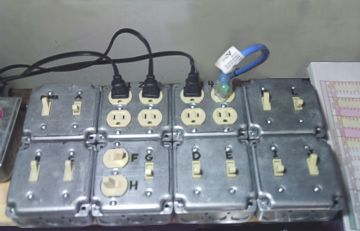 Uses standard NEMA switches and parts (photo at right).
- This system is not polarity-safe and not neutral-safe.
- Provides needed settings for 2, 3, and 4 lamp photoflood switching.
- Provides all 4 single-lamp-on settings, plus off.
- Provides all 11 possible parallel settings.
- Provides all 11 possible series settings.
- Provides 13 series-parallel, 10 parallel-series, and 5 other settings.
- Page author's unit is in use controlling infrared lamp output.
- SP-STD 3
 A neutral-safe polarity-safe configuration
- SP-STD 3 is two SP-STD 2 circuits cascaded. The SP-STD 2 is the basic unit for
these.
- All lamps are connected so that the screw shell is always switched to the neutral
bus when switches are set for lamps in parallel.
- Not all switch connections to the hot bus are throw terminals.
- All switch connections to the neutral bus are throw terminals.
- There are no interconnection buses.
- Double-pole switches are used to enforce polarity-safety and neutral-safety.
- There are no switch ladders.
- Provides needed settings for 2 and 3 lamp photoflood switching.
- Provides all 3 single-lamp-on settings.
- Provides all 4 possible parallel settings.
- Provides all 4 possible series settings.
- Cannot provide all series-parallel or parallel-series circuits.
- This neutral-safe system cannot provide bridge circuits.
- SEPAR 330
 A regular switching matrix
- All switch poles are connected to lamp terminals or cascaded to lamp terminals.
- All lamps are connected so that the screw shell is always switched to the neutral
bus when switches are set for lamps in parallel.
- All switch connections to the hot bus are throw terminals.
- All switch connections to the neutral bus are throw terminals.
- All switch connections to interconnection buses are throw terminals.
- The switch ladders are alternate splitting versions using double-pole switches.
- This system is not polarity-safe and not neutral-safe.
- All lamp channels are alike.
- Provides (but hard-to-find) needed settings for 2 and 3 lamp photoflood switching.
- Provides all 3 single-lamp-on settings, plus off.
- Provides all 4 possible parallel settings.
- Provides all 4 possible series settings.
- Provides all possible series-parallel and parallel-series settings.
- This regular system cannot provide bridge circuits.
- SEPAR I-4
 An infinite switching matrix
- All switch poles are connected to lamp terminals or cascaded to lamp terminals.
- Lamps are NOT always connected so that the screw shell is switched to the neutral
bus when switches are set for lamps in parallel.
- All switch connections to the hot bus are throw terminals.
- All switch connections to the neutral bus are throw terminals.
- All switch connections to interconnection buses are throw terminals.
- There are 3 interconnection buses (one less than the number of lamps).
- All switches are in switch ladders. Each column is a ladder.
- This system is not polarity-safe and not neutral-safe.
- All lamp channels are alike.
- Provides (but hard-to-find) needed settings for 2, 3, and 4 lamp photoflood
switching.
- The polarities of all lamps can be reversed, multiplying numbers of settings.
- Provides all 8 single-lamp-on settings, plus off.
- Provides all 72 possible parallel setting permutations.
- Provides all 624 possible series setting permutations.
- Provides all possible series-parallel and parallel-series settings.
- This infinite system provides no bridge circuits because they require at least 5
lamps.
- The 40 switches can be set to 1,099,511,627,776 positions, but only 1,679,616
are not ladder redundant.
- SEPAR I-5
 An infinite switching matrix
- All switch poles are connected to lamp terminals or cascaded to lamp terminals.
- Lamps are NOT always connected so that the screw shell is switched to the neutral
bus when switches are set for lamps in parallel.
- All switch connections to the hot bus are throw terminals.
- All switch connections to the neutral bus are throw terminals.
- All switch connections to interconnection buses are throw terminals.
- There are 4 interconnection buses (one less than the number of lamps).
- All switches are in switch ladders. Each column is a ladder.
- This system is not polarity-safe and not neutral-safe.
- All lamp channels are alike.
- This version uses standard NEMA switches and parts (image at right).
- Provides (but hard-to-find) needed settings for 2, 3, 4, and 5 lamp photoflood
switching.
- The polarities of all lamps can be reversed, multiplying numbers of settings.
- Provides all 10 single-lamp-on settings, plus off.
- Provides all 232 possible parallel setting permutations.
- Provides all 6320 possible series setting permutations.
- Provides all possible series-parallel and parallel-series setting permutations.
- This infinite system provides all possible bridge circuits.
- Used for the proof
that a switching circuit with all possibilities can't be polarity safe or neutral safe.
- The 60 switches can be set to 1,152,921,504,606,846,976 positions, but only 282,475,249
are not ladder redundant.
- SEPAR I-n
- An infinite switching matrix
- All switch poles are connected to lamp terminals or cascaded to lamp terminals.
- Lamps are NOT always connected so that the screw shell is switched to the neutral
bus when switches are set for lamps in parallel.
- All switch connections to the hot bus are throw terminals.
- All switch connections to the neutral bus are throw terminals.
- All switch connections to interconnection buses are throw terminals.
- There are n-1 interconnection buses (one less than the number of lamps).
- All lamp channels are alike.
- All switches are in 2n switch ladders of n+1 switches each. Each column is a ladder.
- Each switch ladder can be replaced with a rotary switch with n+2 positions (throws).
- Each lamp channel has 2 switch ladders of n+1 switches each.
- One switch ladder feeds the lamp's center terminal. The other feeds its screw shell.
- Each switch ladder can be replaced with a rotary switch with n+2 positions (throws).
- This system is not polarity-safe and not neutral-safe.
- This version uses standard NEMA switches and parts (image above right).
- Provides (but hard-to-find) needed settings for up to n lamp photoflood
switching.
- The polarities of all lamps can be reversed, multiplying numbers of settings.
- Provides all 2n single-lamp-on settings, plus off.
- Provides all possible parallel setting permutations (see table).
- Provides all possible series setting permutations (see table.)
- Provides all possible series-parallel and parallel-series setting permutations.
- This infinite system provides all possible bridge circuits.
- See the table to find number of switches, number of switch permutations, and number of
positions that are not ladder-redundant.
- The SEPAR I series can be expanded to any number of lamps by adding one transfer bus
and one lamp with its two switch ladders for each extra lamp.
#
Lamp |
Rotary
Sws |
Sw Pos
/ Rot Sw |
Sw Pos
Rotary Tot |
#
Lads |
Sws /
Lad |
Sw Pos
/ Lad |
# Lad
Sws |
Sw Pos
Lad Cal |
Sw Pos
Ladders Total |
Good
Pos/Lad |
Good Pos
Lad Cal |
Good Pos
Ladders Tot |
Series
Min |
Parallel
Min |
Series
Total |
Parallel
Total |
| n |
2n |
n+2 |
(n+2) 2n |
2n |
n+1 |
2 n+1 |
2n (n+1) |
2 2n (n+1) |
2 2n (n+1) |
n+2 |
(n+2) 2n |
(n+2) 2n |
2 n - n - 1 |
2 n - n - 1 |
n
∑ (P(n,r) 2r)
r=0
|
n
∑ (C(n,r) 2r)
r=0
|
| 2 |
4 |
4 |
256 |
4 |
3 |
8 |
12 |
2 12 |
4096 |
4 |
4 4 |
256 |
1 |
1 |
8 |
4 |
| 3 |
6 |
5 |
15625 |
6 |
4 |
16 |
24 |
2 24 |
16777216 |
5 |
5 6 |
15625 |
4 |
4 |
72 |
20 |
| 4 |
8 |
6 |
1679616 |
8 |
5 |
32 |
40 |
2 40 |
1099511627776 |
6 |
6 8 |
1679616 |
11 |
11 |
624 |
72 |
| 5 |
10 |
7 |
282475249 |
10 |
6 |
64 |
60 |
2 60 |
1152921504606846976 |
7 |
7 10 |
282475249 |
26 |
26 |
6320 |
232 |
- SP BAT 3
 Multipole switching for special devices
- All switch poles are connected to loads when charging.
- All switch connections to the hot bus are throw terminals.
- All switch connections to the neutral bus are throw terminals.
- There are no interconnection buses.
- There are no switch ladders.
- This system is polarity-safe, but not neutral-safe.
- Provides no settings for photoflood switching.
- Has only one switch for foolproof operation.