4-PHASE SINGLE LAG WITH FLASHING YELLOW ARROWS
THIS SEQUENCE IS A NORMAL LAG TURN PHASE WITH SPECIAL DISPLAYS
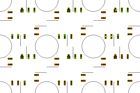
Instead of the normal displays for the left turn, special signal faces with flashing yellow arrows are provided for left-turning traffic. The flashing yellow arrow is shown to left-turning traffic when it is allowed to turn through gaps in oncoming traffic. This allows the flashing arrow to continue to be displayed during and after the yellow clearance of the shorter straight-ahead green, and all the way to the end of the lag left-turn phase. It thus moves the clearance of the left turns to the end of the lag left-turn phase, removing the yellow-trap problem.
How flashing yellow arrows works:
SINGLE LAG WITH FLASHING YELLOW ARROWS
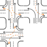
The diagram below shows the phase sequence of traffic flow for a single lag with all-red clear (quick animation).
The diagram on the right shows the signal display sequence used (slow animation to show clearance intervals).


SINGLE LAG PHASE ORDER
The single lag sequence normally operates in the following manner:
- Assuming traffic is waiting to use them, straight-ahead phases 2 and 6 operate first.
- When straight-ahead phase 2 runs out of traffic, it ends with clearance periods, and the lag left-turn phase 1 begins, overlapping phase 6.
- When the lag phase runs out of traffic, the lag and overlap phases terminate with simultaneous clearance periods.
- The side street phase has its period.
Parts of the above sequence can be omitted. For example, the main street could start with the left turn and the adjacent straight-ahead movement.
The left-turn signal heads are modified with the flashing arrow display, which keep the yellow-trap hazard can not occur.
The numbers on the diagram are phase numbers.

(2 6)

(2 5)

(4)
SINGLE LAG WITH FLASHING YELLOW ARROW
- This is used with either the 3-light protected or the special 5-light protected/permissive left-turn display (see diagrams at right) for the left turn phase. Because the left turn that would otherwise be trapped does not have a left turn phase, the display type does not matter.
- The left turn that would otherwise be trapped has the special 3-light signal face shown, which prevents the yellow-trap hazard by extending the permissive turn to the end of the lag turn phase.
- Special signal faces are necessary. The permissive aspects of the 5-light signal do NOT display the same aspects as the adjacent straight-ahead signals. Instead, they display the aspects of the oncoming straight-ahead signals. But the permissive aspects are darkened by the presence of the protected aspects by special circuitry.
- The wiring for this system is not standard. Extra circuits are needed on each mast arm or span wire for the permissive indications, since they are not the same circuits the adjacent straight-ahead signals use. And special signal driver circuits are needed. But no changes are needed in either the phase order or the detector connections.
- The 2009 MUTCD (Manual of Uniform Traffic Control Devices) was changed to allow this use of flashing yellow arrows.
- This sequence is the most effective at preventing yellow-trap.
| Signal faces used with this method | |
|---|---|
| Standard 3-light signal face for left turns that are always protected: |

|
| Special 4-light signal face for left turns that are both permissive and protected: The top yellow arrow is for clearance, the bottom one flashes for the permissive turn. It has the same function as the face below, but clearance of the permissive turn is not as obvious. |

|
| Special 5-light signal face for left turns that are both permissive and protected: The left side of the signal face is for the protected turn, the right side is for the permissive turn. The yellow arrow on the right flashes for the permissive turn. Not approved by MUTCD. |

|
| Special 3-light signal for completely permissive left turns oncoming to any of the above displays: The lower yellow arrow flashes for the permissive turn. |

|
| Standard signal for all straight-ahead indications, and left turns on streets without any left-turn phases: |

|
FLASHING YELLOW ARROWS
The phase order of a quad split lead sequence is shown. The quad left-turn sequence and dual-ring controller are explained here.
In the flashing yellow arrows sequence, the standard lagging turn controller programming is used.
The flashing yellow arrows sequence changes only the signals displayed, not the controller sequence.
| PHASE TABLE | ||||
|---|---|---|---|---|
| Timing Rings: | TR-1 (2 4) | TR-2 (5 6) | ||
| Concurrency: | CG-1 (2 5 6) | CG-2 (4) | ||
| Timing groups: | TG-1 (2 6) | TG-2 (5) | TG-3 (4) | |
| Overlap pairs: | (2 6) | (2 5) | ||
| EXTRA OVERLAP PHASE TABLE | ||||
|---|---|---|---|---|
| Overlap unit | Parent phases | Conditions | ||
| OV-A | 2 | |||
| OV-B | - | |||
| OV-C | 6 5 | Dark when phase 6 is green or yellow | ||
| OV-D | - | |||
| A,C | - | Green is flashing yellow arrow | ||
| PHASE DIAGRAM | ||||||||
|---|---|---|---|---|---|---|---|---|
| |
Ring 1 |
|
 |
|
Ring 2 |
|
|
|
| |
|
|
|
|
|
|||
| TG-1 |  Phase 2 Phase 2 |
OV-A | OV-C |  Phase 6 Phase 6 |
|
|
||
| | | CG-1 | |
|
|
|
|
||||
| TG-2 | |
|
|
|
 Phase 5 Phase 5 |
|
|
|
| |
|
|
|
|
|
|||
| |
BARRIER | |
 |
|
|
BARRIER |
|
|
| | | CG-2 | |
|
|
|
|
|
|
||
| TG-3 |  Phase 4 Phase 4 |
|
|
|
|
|
|
|
| |
 |
|
|
|
|
|
|
|
| |
|
|
|
|
|
|
|
|
| |
BARRIER | |
 |
|
|
BARRIER | |
|
| |
|
|
|
|
|
|
|
|
INTERFACING THE INTERSECTION
FLASHING YELLOW ARROWS
| DETECTOR | ||||
|---|---|---|---|---|
| Detector | Normal phase |
Redirect phase | Redirect when | |
| - | - | |||
| 2 | 2 | - | ||
| - | - | |||
| 4 | 4 | - | ||
| 5 | 5 | - | ||
| 6 | 6 | - | ||
| - | - | |||
| - | - | |||
| SIGNAL FACE TABLE | ||||
|---|---|---|---|---|
| Face | Phase | Modifier | ||
| - | ||||
| 2 | 2 | |||
| - | ||||
| 4 | 4 | |||
| 5 | 5 | No red indication (phase C in same face) | ||
| 6 | 6 | |||
| - | ||||
| - | ||||
| A | OV-A | |||
| B | - | |||
| C | OV-C | Dark if phase 5 is green or yellow | ||
| D | - | |||
| INTERSECTION DIAGRAM | ||||||||
|---|---|---|---|---|---|---|---|---|
| |
|
|
|
|
|
|
|
|
| |
|
|
 |
 |
 |
|
|
|
| |
|
|
6 | 6 |  |
|
|
|
| |
|
|
 |
|5|C| | |2| | |
|
|
 |
|
|4| |  |
 |
 |
|
4 |  |
 |
4 | |4| |  |
 |
 |
|4| | 4 |  |
 |
4 | |
 |
 |
 |
|4| | |
 |
| |
|
|
|6| | |A| |  |
|
|
|
| |
|
|
 |
5 | 2 | |
|
|
| |
|
|
 |
 |
 |
|
|
|
| |
|
|
|
|
|
|
|
|
Detectors are blue. Signal faces are orange.
SINGLE LAG WITH FLASHING YELLOW ARROWS
ADVANTAGES
- Allows the safe use of a lag left-turn phase.
- Phase skip prevents wasting time at empty approaches.
- Can be used at a simultaneous node or offset from a simultaneous node in a progression system.
- No change in the phasing is needed to add flashing yellow arrows.
- The system works with all phase orders.
- The system works with all signal pre-emption schemes.
- The order of phases can be altered to make other sequences without causing yellow-trap.
- The system allows the use of phase orders that would not otherwise be considered.
- Meets federal standards.
- Can not yellow-trap if used properly.
SINGLE LAG WITH FLASHING YELLOW ARROWS
DISADVANTAGES
- Needs special signal display logic and extra signal circuits.