STANDARD 8-PHASE QUAD LEFT-TURN SEQUENCE
THIS SEQUENCE HAS BEEN IN USE SINCE THE MID 1960S
The quad split lead left-turn sequence has been in use for years, It is the standard way traffic signals are installed when left-turn phases are needed in all four directions. If phase skip is allowed, and one entire street is skipped, this sequence can cause the yellow-trap hazard.
How the 8-phase quad left-turn sequence works:
THE NORMAL QUAD LEFT-TURN SEQUENCE
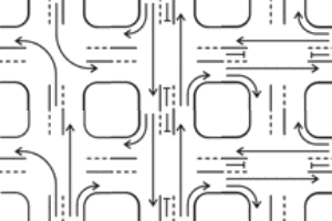
The diagram on the near right shows a quad split lead with left turns allowed only when the protected left-turn phase is active.
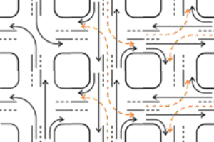
The far right diagram shows a quad split lead sequence where left turns are allowed to filter through gaps in traffic when shown a circular green (orange broken lines). It also shows the hazard of yellow-trap collisions (red)


QUAD LEFT-TURN PHASE ORDER
The quad left-turn sequence (quad split lead) normally operates in the following manner:
- Assuming traffic is waiting to use them, both left-turn phases on one street operate first.
- When one left-turn phase runs out of traffic, it ends with clearance periods, and the oncoming straight-ahead phase is released.
- When the other left-turn phase runs out of traffic, it also ends with clearance periods, and the oncoming straight-ahead phase is released. Now both straight-ahead phases are moving traffic.
- When both straight-ahead phases run out of traffic, they terminate with simultaneous clearance periods.
- The same sequence then occurs on the other street
If some of the approaches or phases have no traffic on them, those phases can be skipped. This can cause the following effects:
- Parts of the above sequence can be omitted. For example, the street could start with one left turn and the adjacent straight-ahead movement, or even both straight-ahead movements.
- If one entire street has no traffic waiting, one or both straight-ahead phases can terminate. If left turns are allowed to turn through gaps in oncoming traffic, this can cause the yellow-trap hazard.
The numbers on the diagram are phase numbers.

(1 5)


(1 6) ||||| (2 5)

(2 6)

(3 7)


(4 7) ||||| (3 8)

(4 8)
BASIC QUAD LEFT SYSTEM
- Either the 3-light protected display or the 5-light protected/permissive display is used for left-turn displays (see diagrams at right).
- All signal faces are standard.
- The circular aspects of the 5-light signal display the same aspects as the adjacent straight-ahead signals.
- The wiring for this system is standardized.
- The MUTCD prescribes this kind of signal.
- The protected version can't yellow-trap.
- The protected/permissive version has no protection against yellow-trap from phase skip
| Signal faces used with this method | |
|---|---|
| Standard 3-light signal face for left turns that are always protected: |

|
| Standard 5-light signal face for left turns that are both permissive and protected: |

|
| Standard 3-light signal for completely permissive left turns oncoming to either of the above displays: |

|
| Standard signal for all straight-ahead indications, and left turns on streets without left-turn phases: |

|
How dual ring controllers work:
DUAL RING CONTROLLER
The phase order of a dual-ring controller is shown. The following facts apply:
- A phase is the portion of the controller that operates the set of signals for one traffic movement. The arrow inside each phase box shows the traffic movement the phase services.
- A phase is active if it is displaying a green, yellow, WALK, or flashing DON'T WALK, or timing a red clearance interval.
- A timing ring is the element of the controller that handles the timing of a set of phases. Only one phase in a timing ring may be active at any one time. The timing ring's timer handles the timing for the active phase in the ring.
- A phase can overlap another phase if it can be active at the same time the other phase is active.
- A CG (concurrency group) is a set of phases. Within the CG, any phase in one ring can overlap any phase in the other ring. Both timing ring timers must be in the same CG at the same time.
- Concurrency groups are separated by barriers. Both timing rings must cross barriers at the same time.
- A TG (timing group) is as division used to determine the order phases are displayed in. The controller advances the timers from TG to TG in the direction of the large arrows.
- Phase numbers correspond to those of a standard NEMA 8-phase setup for a quad-lead left-turns sequence. Note that, to comply with the NEMA standard, phase 2 must be northbound or eastbound on the major road.
- A dual ring controller has two timing rings (Ring 1 and Ring 2), and at least two concurrency groups (CG).
- For phases that are in the same concurrency group, any phase in one timing ring can overlap any phase in the other timing ring.
- A phase must belong to exactly one timing ring, one timing group, and one concurrency group.
- For smaller setups, unused phases are shut off, and do not affect the rest of the cycle.
| PHASE DIAGRAM | ||||||||
|---|---|---|---|---|---|---|---|---|
| |
Ring 1 |
|
 |
|
Ring 2 |
|
|
|
| |
|
|
|
|
|
|||
| TG-1 |  Phase 1 Phase 1 |
|
|
 Phase 5 Phase 5 |
|
|
||
| | | CG-1 | |
|
|
|
|
||||
| TG-2 |  Phase 2 Phase 2 |
|
|
 Phase 6 Phase 6 |
|
|
||
| |
|
|
|
|
|
|||
| |
BARRIER | |
 |
|
|
BARRIER |
|
|
| |
|
|
|
|
|
|||
| TG-3 |  Phase 3 Phase 3 |
|
|
 Phase 7 Phase 7 |
|
|
||
| | | CG-2 | |
|
|
|
|
||||
| TG-4 |  Phase 4 Phase 4 |
|
|
 Phase 8 Phase 8 |
|
|
||
| |
|
|
|
|
|
|||
| |
BARRIER | |
 |
|
|
BARRIER | |
|
| |
|
|
|
|
|
|
|
|
| PHASE TABLE | ||||
|---|---|---|---|---|
| Timing Rings: | TR-1 (1 2 3 4) | TR-2 (5 6 7 8) | ||
| Concurrency: | CG-1 (1 2 5 6) | CG-2 (3 4 7 8) | ||
| Timing groups: | TG-1 (1 5) | TG-2 (2 6) | TG-3 (3 7) | TG-4 (4 8) |
| Overlap pairs: | (1 5) | (1 6) | (2 5) | (2 6) |
| Overlap pairs: | (3 7) | (3 8) | (4 7) | (4 8) |
| EXTRA OVERLAP PHASE TABLE | ||||
|---|---|---|---|---|
| Overlap unit | Parent phases | Conditions | ||
| OV-A | - | |||
| OV-B | - | |||
| OV-C | - | |||
| OV-D | - | |||
INTERFACING THE INTERSECTION
PROTECTED
| DETECTOR | ||||
|---|---|---|---|---|
| Detector | Normal phase |
Redirect phase | Redirect when | |
| 1 | 1 | - | ||
| 2 | 2 | - | ||
| 3 | 3 | - | ||
| 4 | 4 | - | ||
| 5 | 5 | - | ||
| 6 | 6 | - | ||
| 7 | 7 | - | ||
| 8 | 8 | - | ||
| SIGNAL FACE TABLE | ||||
|---|---|---|---|---|
| Face | Phase | Modifier | ||
| 1 | 1 | |||
| 2 | 2 | |||
| 3 | 3 | |||
| 4 | 4 | |||
| 5 | 5 | |||
| 6 | 6 | |||
| 7 | 7 | |||
| 8 | 8 | |||
| INTERSECTION DIAGRAM | ||||||||
|---|---|---|---|---|---|---|---|---|
| |
|
|
|
|
|
|
|
|
| |
|
|
 |
 |
 |
|
|
|
| |
|
|
6 | 1 |  |
|
|
|
| |
|
|
 |
|5| | |2| | |
|
|
 |
|
|8| |  |
 |
 |
|
8 |  |
 |
7 | |3| |  |
 |
 |
|7| | 3 |  |
 |
4 | |
 |
 |
 |
|4| | |
 |
| |
|
|
|6| | |1| |  |
|
|
|
| |
|
|
 |
5 | 2 | |
|
|
| |
|
|
 |
 |
 |
|
|
|
| |
|
|
|
|
|
|
|
|
Detectors are blue. Signal faces are orange.
INTERFACING THE INTERSECTION
PROTECTED/PERMISSIVE
| DETECTOR | ||||
|---|---|---|---|---|
| Detector | Normal phase |
Redirect phase | Redirect when | |
| 1 | 1 | - | ||
| 2 | 2 | - | ||
| 3 | 3 | - | ||
| 4 | 4 | - | ||
| 5 | 5 | - | ||
| 6 | 6 | - | ||
| 7 | 7 | - | ||
| 8 | 8 | - | ||
| SIGNAL FACE TABLE | ||||
|---|---|---|---|---|
| Face | Phase | Modifier | ||
| 1 | 1 | No red indication (phase 6 in same face) | ||
| 2 | 2 | |||
| 3 | 3 | No red indication (phase 8 in same face) | ||
| 4 | 4 | |||
| 5 | 5 | No red indication (phase 2 in same face) | ||
| 6 | 6 | |||
| 7 | 7 | No red indication (phase 4 in same face) | ||
| 8 | 8 | |||
| INTERSECTION DIAGRAM | ||||||||
|---|---|---|---|---|---|---|---|---|
| |
|
|
|
|
|
|
|
|
| |
|
|
 |
 |
 |
|
|
|
| |
|
|
6 | 1 |  |
|
|
|
| |
|
|
 |
|5|2| | |2| | |
|
|
 |
|
|8| |  |
 |
 |
|
8 |  |
 |
7 | |8| |3| |
 |
 |
 |
|7| |4| |
3 |  |
 |
4 | |
 |
 |
 |
|4| | |
 |
| |
|
|
|6| | |6|1| |  |
|
|
|
| |
|
|
 |
5 | 2 | |
|
|
| |
|
|
 |
 |
 |
|
|
|
| |
|
|
|
|
|
|
|
|
Detectors are blue. Signal faces are orange.
STANDARD QUAD SEQUENCE
ADVANTAGES
- Maximizes time use at isolated intersection.
- Phase skip prevents wasting time at empty approaches.
- Conforms to driver expectation of phase sequence.
- Can be used at a simultaneous node in a progression system.
STANDARD QUAD SEQUENCE
DISADVANTAGES
- The protected/permissive version can yellow-trap.
- Can not be used away from a simultaneous node in a progression system.