8-PHASE QUAD LEFT-TURN WITH FLASHING YELLOW ARROWS
THIS MODIFIES THE DISPLAY OF THE STANDARD QUAD LEFT TURN SEQUENCE TO PREVENT YELLOW-TRAP
The quad split lead left-turn sequence has been in use for years, It is the standard way traffic signals are installed when left-turn phases are needed in all four directions. If phase skip is allowed with permissive left-turns, and one entire street is skipped, this sequence can cause the yellow-trap hazard. But a change in the way the signals are displayed can prevent the conflict, by delaying it until the oncoming traffic is also stopped.
How the flashing yellow arrows quad left-turn sequence works:
THE QUAD LEFT-TURN SEQUENCE WITH FLASHING YELLOW ARROWS
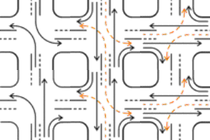
The diagram on the near right shows a quad split lead where left turns are allowed to filter through gaps in traffic when shown a circular green (orange broken lines). It also shows the hazard of yellow-trap collisions (red).
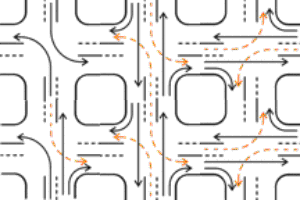
The far right diagram shows a quad split lead sequence where flashing yellow arrows extend the permissive left turn until it can be safely terminated.


QUAD LEFT-TURN PHASE ORDER
The quad left-turn sequence (quad split lead) operates in the following manner:
- If traffic is waiting to use them, both left-turn phases on one street operate first.
- When one left-turn phase runs out of traffic, it ends with clearance periods, and the oncoming straight-ahead phase is released.
- When the other left-turn runs out of traffic, it also ends with clearance periods, and its oncoming straight-ahead phase is released. Now both straight-ahead phases are moving traffic.
- When both straight-ahead phases run out of traffic, they terminate with simultaneous clearance periods.
- The same sequence then occurs on the other street.
If some of the approaches or phases have no traffic on them, those phases can be skipped. This can cause the following effects:
- Parts of the sequence can be omitted. One street could start with one left turn and the adjacent straight-ahead movement, or even both straight-ahead movements.
- If one entire street has no traffic waiting, one or both straight-ahead phases can terminate. If left turns are allowed to turn through gaps in oncoming traffic, this can cause the yellow-trap hazard. But the flashing yellow arrows modification eliminates the hazard, as shown in the diagram at right.
The numbers on the diagram are phase numbers.

(1 5)


(1 6) ||||| (2 5)

(2 6)

(3 7)


(4 7) ||||| (3 8)

(4 8)
QUAD LEFT WITH FLASHING YELLOW ARROWS
- Special 5-light protected/permissive displays with flashing yellow arrows are used for left-turn displays (see diagrams at right).
- Special signal faces are used. The permissive aspects of the 5-light signal do NOT display the same aspects as the adjacent straight-ahead signals. Instead, they display the aspects of the oncoming straight-ahead signals. But the permissive aspects are darkened by the presence of the protected aspects by special circuitry.
- The wiring for this system is not standard. Extra circuits are needed on each mast arm or span wire for the permissive indications, since they are not the same circuits the adjacent straight-ahead signals use. And special signal driver circuits are needed. But no changes are needed in either the phase order or the detector connections.
- The 2009 MUTCD (Manual of Uniform Traffic Control Devices) was changed to allow this use of flashing yellow arrows.
- This sequence is the most effective at preventing yellow-trap.
| Signal faces used with this method | |
|---|---|
| Standard 3-light signal face for left turns that are always protected: |

|
| Special 4-light signal face for left turns that are both permissive and protected: The top yellow arrow is for clearance, the bottom one flashes for the permissive turn. It has the same function as the face below, but clearance of the permissive turn is not as obvious. |

|
| Special 5-light signal face for left turns that are both permissive and protected: The left side of the signal face is for the protected turn, the right side is for the permissive turn. The yellow arrow on the right flashes for the permissive turn. Not approved by MUTCD. |

|
| Special 3-light signal for completely permissive left turns oncoming to any of the above displays: The lower yellow arrow flashes for the permissive turn. |

|
| Standard signal for all straight-ahead indications, and left turns on streets without any left-turn phases: |

|
FLASHING YELLOW ARROWS
The phase order of a quad split lead sequence is shown. The quad left-turn sequence and dual-ring controller are explained here.
In the flashing yellow arrows sequence, the standard quad split lead turn controller programming is used.
The flashing yellow arrows sequence changes only the signals displayed, not the controller sequence.
| PHASE TABLE | ||||
|---|---|---|---|---|
| Timing Rings: | TR-1 (1 2 3 4) | TR-2 (5 6 7 8) | ||
| Concurrency: | CG-1 (1 2 5 6) | CG-2 (3 4 7 8) | ||
| Timing groups: | TG-1 (1 5) | TG-2 (2 6) | TG-3 (3 7) | TG-4 (4 8) |
| Overlap pairs: | (1 5) | (1 6) | (2 5) | (2 6) |
| Overlap pairs: | (3 7) | (3 8) | (4 7) | (4 8) |
| EXTRA OVERLAP PHASE TABLE | ||||
|---|---|---|---|---|
| Overlap unit | Parent phases | Conditions | ||
| OV-A | 2 | Dark when phase 1 is green or yellow | ||
| OV-B | 4 | Dark when phase 3 is green or yellow | ||
| OV-C | 6 | Dark when phase 5 is green or yellow | ||
| OV-D | 8 | Dark when phase 7 is green or yellow | ||
| A,B,C,D | - | Green is flashing yellow arrow | ||
| PHASE DIAGRAM | ||||||||
|---|---|---|---|---|---|---|---|---|
| |
Ring 1 |
|
 |
|
Ring 2 |
|
|
|
| |
|
|
|
|
|
|||
| TG-1 |  Phase 1 Phase 1 |
|
|
 Phase 5 Phase 5 |
|
|
||
| | | CG-1 | |
|
|
|
|
||||
| TG-2 |  Phase 2 Phase 2 |
OV-A | OV-C |  Phase 6 Phase 6 |
|
|
||
| |
|
|
|
|
|
|||
| |
BARRIER | |
 |
|
|
BARRIER |
|
|
| |
|
|
|
|
|
|||
| TG-3 |  Phase 3 Phase 3 |
|
|
 Phase 7 Phase 7 |
|
|
||
| | | CG-2 | |
|
|
|
|
||||
| TG-4 |  Phase 4 Phase 4 |
OV-B | OV-D |  Phase 8 Phase 8 |
|
|
||
| |
|
|
|
|
|
|||
| |
BARRIER | |
 |
|
|
BARRIER | |
|
| |
|
|
|
|
|
|
|
|
INTERFACING THE INTERSECTION
FLASHING YELLOW ARROWS
| DETECTOR | ||||
|---|---|---|---|---|
| Detector | Normal phase |
Redirect phase | Redirect when | |
| 1 | 1 | - | ||
| 2 | 2 | - | ||
| 3 | 3 | - | ||
| 4 | 4 | - | ||
| 5 | 5 | - | ||
| 6 | 6 | - | ||
| 7 | 7 | - | ||
| 8 | 8 | - | ||
| SIGNAL FACE TABLE | ||||
|---|---|---|---|---|
| Face | Phase | Modifier | ||
| 1 | 1 | No red indication (phase A in same face) | ||
| 2 | 2 | |||
| 3 | 3 | No red indication (phase B in same face) | ||
| 4 | 4 | |||
| 5 | 5 | No red indication (phase C in same face) | ||
| 6 | 6 | |||
| 7 | 7 | No red indication (phase D in same face) | ||
| 8 | 8 | |||
| A | OV-A | Dark when phase 1 is green or yellow | ||
| B | OV-B | Dark when phase 3 is green or yellow | ||
| C | OV-C | Dark when phase 5 is green or yellow | ||
| D | OV-D | Dark when phase 7 is green or yellow | ||
| INTERSECTION DIAGRAM | ||||||||
|---|---|---|---|---|---|---|---|---|
| |
|
|
|
|
|
|
|
|
| |
|
|
 |
 |
 |
|
|
|
| |
|
|
6 C | 1 |  |
|
|
|
| |
|
|
 |
|5|C| | |2| | |
|
|
 |
|
|8| |  |
 |
 |
|
8 D |
 |
 |
7 | |B| |3| |
 |
 |
 |
|7| |D| |
3 |  |
 |
4 B |
|
 |
 |
 |
|4| | |
 |
| |
|
|
|6| | |A|1| |  |
|
|
|
| |
|
|
 |
5 | 2 A | |
|
|
| |
|
|
 |
 |
 |
|
|
|
| |
|
|
|
|
|
|
|
|
Detectors are blue. Signal faces are orange.
QUAD LEFT WITH FLASHING YELLOW ARROWS
ADVANTAGES
- Allows the safe use of phase skip or yellow phases.
- Phase skip prevents wasting time at empty approaches.
- Can be used at a simultaneous node in a progression system as is.
- No change in the phasing is needed to add flashing yellow arrows.
- The system works with all phase orders.
- The system works with all signal pre-emption schemes.
- The order of phases can be altered to make other sequences without causing yellow-trap.
- The system allows the use of phase orders that would not otherwise be considered.
- Meets federal standards.
- Can not yellow-trap if used properly.
QUAD LEFT WITH FLASHING YELLOW ARROWS
DISADVANTAGES
- Needs special signal display logic and extra signal circuits.