Vertical and Lateral Recording
Note that the point of view for the groove diagram and the stylus motion diagrams is from where a person normally stands when playing a record with the arm mounted in the usual place on the right side of the turntable. The viewer is looking at the active end of the stylus and cartridge. The outside wall of the groove (toward the record rim) is on the right, and the inside wall (toward the spindle) is on the left.

The first phonograph recordings were made with the vertical, or hill and dale method. This caused the groove made by the recording cutter to be modulated vertically. The groove became deeper and shallower as the sound waves modulated it. This causes the playback stylus to vibrate in a vertical direction, as shown by the violet arrow. Of course, the arrow is exaggerated in size - the stylus could not possibly vibrate more than a third of the depth of the groove without causing groove tracking trouble.
Later recordings (including most 78 rpm records, and all mono LPs and 45s) were recorded laterally. The stylus vibrates from side to side, as shown by the green arrow. This modulation is also used for sounds centered between the speakers in a stereo recording.
The head of each arrow shows the modulation direction on an increase in sound pressure. A decrease in pressure moved the stylus the other way.
Poincaré Sphere
modulations
explained below
Lateral can be played on any stereo phonograph, provided the proper size stylus is used.
To play vertical records, either a phase reversal of one stereo channel is needed, or the surround output of a Dolby Surround system can be used.
- Lateral = .71L + .71R
- Vertical = .71R - .71L
Capital letters indicate stereo channels. Lowercase letters indicate quadraphonic channels.
Westrex 45-45 system

Stereo phonograph recordings use stylus motions at 45° angles to horizontal. With a V-shaped groove, the left wall of the groove (as seen from the front of the phonograph) carries the left channel. This is the wall closest to the spindle. The right wall of the groove (the wall closest to the record rim) carries the right channel. For sounds between the speakers, the modulations become shallower, becoming lateral for sounds centered between the speakers.
On the Poincaré sphere, the left channel modulation is on the far side of the sphere. The right channel modulation is on the near side. A small circle shows a modulation plotted on the near (right channel) side of the sphere. A larger circle denotes a modulation plotted on the far side (left channel) of the sphere.
Poincaré Sphere
Stereo records can be played on any stereo phonograph, provided the proper size stylus is used.
A "Three Channel" recording used three mics. The third mic (f) was fed equally to both channels of the record, producing a lateral modulation. This plays on any stereo.
- l = L
- r = R
- f = .71L + .71R
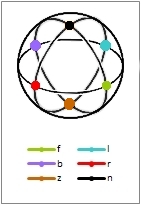
The Six Primary Orthogonal Modulations
(Hexaphonic Tridee modulation letters shown)
- Lateral motion (f) is olive green.
- Vertical motion (b) is violet.
- Left channel motion (l) is cyan (inner groove wall).
- Right channel motion (r) is red (outer groove wall).
- Clockwise motion (n) is a clockwise circle.
- Anticlockwise motion (z) is an anticlockwise circle.
- Odd angle & elliptical motions are in between.
- All motions are in the plane of stylus motion.
- All motions are found on the Poincaré Sphere (right).
- Angles between linear stylus motions are half the sphere angles.
Orthogonal Modulations
Any two modulations are orthogonal if they are 180° apart on the surface of the Poincaré Sphere.
- Two orthogonal modulations do not interact.
- Two modulations that are not orthogonal interact.
Modulations that interact have reduced separations.
- Two modulations 180° apart have infinite separation.
- Two modulations 135° apart have a 8.3 dB separation.
- Two modulations 120° apart have a 6.0 dB separation.
- Two modulations 90° apart have a 3.0 dB separation.
- Two modulations 60° apart have a 1.2 dB separation.
- Two modulations 45° apart have a 0.7 dB separation.
- Two modulations 0° apart have a 0.0 dB separation.
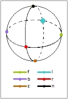
The Poincaré Sphere (also called the Stokes Sphere, the Foucault Sphere, and the Fresnel Sphere) was originally conceived by Henri Poincaré in 1892 to describe polarized light, and by Foucault to describe free-swinging pendulum motion. It was adapted by Peter Scheiber in 1970 to describe the phase relationships between the stereo channels of a recording, and was independently discovered by the page author for the same purpose. All modulations are on the surface of the sphere. The six orthogonal modulations are shown as follows:
- Lateral motion (f) is at the extreme right.
- Vertical motion (b) is at the extreme left.
- Left channel motion (l) is on the far side.
- Right channel motion (r) is on the near side.
- Clockwise motion (n) is at the extreme top.
- Anticlockwise motion (z) is at the extreme bottom.
- Odd angle & elliptical motions are in between.
- Small dots are on the near side of the sphere.
- Large dots are on the far side of the sphere.
L F R

L B R
Modulations 180° apart on the sphere have complete separation. Modulations 90° apart have 3 dB of separation.
The kind of symbol at right is used to show the apparent size and shape of the total sound image.
The listener is seen from above in these diagrams and is facing forward (top of diagram).
If one diagrams is shown, the surround system
does not have a height dimension
If two diagrams are shown, the surround system
also has a height dimension
B Z F L F R
B N F L B R
3-D results
The left diagram is seen from the right side and shows zenith and nadir image shapes.
The right diagram is seen from above and is the same as the single diagram.
Six Orthogonal Poincaré Modulations
Oblique View
Isometric View
The stereo pickup can play any Poincaré Sphere modulation. A decoder recovers the wanted signals and sends them to the proper speakers.
- l = L
- r = R
- f = .71L + .71R
- b = -.71L + .71R
- n = .71L - .71Rj
- z = -.71Lj + .71R
Note that when n is used it means a speaker to the nadir (below the listener).
Note that when z is used it means a speaker to the zenith (above the listener).
The j ConventionThe convention used here is that +j terms are leading phase shifts 90° ahead of the reference signal. Used with the reference signal, they make rotating modulations. A -j term is a 90° lagging phase shift. Another convention has +j lagging the reference signal by 90° and -j leading it. It is not used here. |
 This image represents the listener in speaker
location diagrams.
This image represents the listener in speaker
location diagrams.
Regular Matrix

RM Room
In 1969, Peter Scheiber evenly divided up the spaces between the linear orthogonal motions already described, arriving at the modulations shown. No commercial recordings are known to be recorded in it.
By 1971, Sansui had independently developed what is essentially the same system, which they called QS. It has the second largest discography of surround material, including one movie.
In both cases, speakers are provided for the left front (lf), left back (lb), right front (rf), and right back (rb) signals.
The QS system encoder produced the n (nadir - straight down) modulation when equal signals were presented at all inputs. The z (zenith - straight up) modulation is also possible, but is not normally used.
The Scheiber encoder
- L = .92lf + .38rf + .92lb - .38rb
- R = .92lf + .38rf - .92lb + .38rb
The QS encoder (Σ)
- L = .92lf + .38rf + .92lbj + .38rbj
- R = .92lf + .38rf - .92lbj - .38rbj
Regular Matrix
A Dolby Surround system in the Cinema/Pro-Logic mode plays these recordings, as does any QS or RM decoder. Actually, Pro Logic also does a nice job, as do any of the Dynaco or EV systems.
The Scheiber decoder
- lf = .92L + .38R
- rf = .38L + .92R
- lb = .92L - .38R
- rb = -.38L + .92R
The QS decoder (Σ)
- lf = .92L + .38R
- rf = .38L + .92R
- lb = -.92Lj + .38Rj
- rb = -.38Lj + .92Rj
In the BBC trials, the basic QS matrix was Matrix A, and the QS Variomatrix was Matrix C.
One unique property of QS is that the 4 decoded outputs can be mixed together to produce a mono signal that contains all of the music. No other matrix system can do this.
Dynaco Matrix
In 1970, Dynaco developed a passive matrix decoder, using only the way the speakers are connected to the amplifiers to do the decoding. It uses the four linear orthogonal motions listed above. The Hafler Dynaco Diamond is the simplest and cheapest system available. Anybody can build one with nothing but speakers and resistors.
The major disadvantage at the time was the location of the speakers on the faces of the listening room walls, instead of in the corners. This caused conflicts in room decor and in positioning speakers so they sound best.
Several commercial recordings are known to be recorded in it. The Dynaco Diamond is actually better suited to classical music than most of the other systems. The page author used it in 1971 to produce a set of sound effects for a stage theatrical production.
The Hafler Dynaco diamond encoder (Σ)
- L = .71f + l - .71b
- R = .71f + r + .71b
Dynaco Matrix
A Dolby Surround system in the Cinema or Hall mode plays these recordings, as does any Dynaco Diamond, QS, or RM decoder. Pro Logic also does a nice job, as do any of the Dynaquad or EV systems.
The Hafler Dynaco diamond decoder (Σ)
- l = L
- r = R
- f = .71L + .71R
- b = -.71L + .71R
EV Stereo-4 Encode
EV Stereo-4 Decode

In 1970, Leonard Feldman and Jon Fixler developed what would become the Electro-Voice Stereo-4 system.
This was the first system to use different sets of coefficients for encoding and decoding. (Most other systems have decode coefficients that mirror the encode coefficients.)
It was originally developed as a way to make headphones work with surround sound. Afterward, it was extended to work with speakers.
This is a front-oriented system, because it emphasizes front separation and front-to-back separation, at the expense of back separation. This makes it better suited to classical music than most of the other systems.
Many commercial recordings are recorded with it. It has the 5th largest discography. I have normalized the equations, so all of them have the same amplitudes (the original equations did not).
The EV encoder (Σ)
- L = .96lf + .29rf + .89lb - .45rb
- R = .29lf + .96rf - .45lb + .89rb
EV Stereo-4 Encode
EV Stereo-4 Decode
A Dolby Surround system in the Cinema or Hall mode plays these recordings, as does any Electro-Voice decoder. Pro Logic also does a nice job, as do any of the other Regular Matrix decoders.
The EV decoder (Σ)
- lf = .98L + .20R
- rf = .20L + .98R
- lb = .78L - .62R
- rb = -.62L + .78R
Dynaquad Encode
Dynaquad Decode

DQ

DQ-5
In 1971, Dynaco changed the Dynaco Diamond into the Dynaquad system, which has the speakers in the corners of the room. It is still a passive system. This system also uses different sets of coefficients for encoding and decoding. This is a front-oriented system, because it emphasizes front separation and front-to-back separation, at the expense of back separation.
Few recordings were made in this system. It is better suited to classical music than most of the other systems. I have normalized the equations, so all of them have the same amplitudes (the original equations did not).
This was available in 4-speaker (upper diagram) and 5 speaker (lower diagram) versions.
The Dynaquad encoder (Σ)
- L = .97lf + .24rf + .89lb - .45rb
- R = .24lf + .97rf - .45lb + .89rb
Dynaquad Encode
Dynaquad Decode
Dynaquad Quadaptor
Dynaco sold a $20 decoder called a Quadaptor, to be connected between the amplifier and the speakers.
A Dolby Surround system in the Cinema or Hall mode plays these recordings, as does any Dynaquad decoder. Pro Logic also does a nice job, as do any of the other Regular Matrix decoders.
Quadaptor equations (Σ)
- lf = L
- rf = R
- lb = .86L - .5R
- rb = -.5L + .86R
5-Speaker equations (Σ)
- lf = L
- rf = R
- f = .71L + .71R
- lb = .86L - .5R
- rb = -.5L + .86R
CBS SQ Panpot Encode & Decode

SQ

SQ 10/40
In 1971, Benjamin Bauer, Columbia Records, CBS, and Sony developed the SQ system after experimenting with systems similar to QS and UMX. CBS management required that the system must preserve stereo left-to-right separation. It does this at the expense of front-to-back separation. It is thus not well suited to ambiance recordings of concert halls. This system is unusual in that the back channels are recorded with circular stylus motions.
CBS SQ has the third largest discography.
There are two encoders, pan-potted and 4-corners, each with different modulations for sounds from the sides.
There are two decoders. The 10-40 decoder is cheap, with no logic. The expensive decoder uses the main modulations with signal-steering logic. The second room diagram is for SQ 10-40
SQ 4-corner encoder
- L = lf - .71lbj + .71rb
- R = rf - .71lb + .71rbj
SQ Panpot Encode
Only an SQ decoder or an EV-Universal decoder can decode this right. Dolby Surround and RM decoders decode all but the back corners correctly. They place the back corners in the middle of the room.
SQ basic decoder
- lf = L
- rf = R
- lb = .71Lj - .71R
- rb = .71L - .71Rj
The 10-40 decoder has a 10% blend between the front channels, and a 40% blend between the back channels. It can decode RM and QM, but the full logic one can't.
In the BBC trials, the 10-40 SQ matrix was Matrix B, and the SQ Full Logic was Matrix D.
CBS SQ 10-40 Decode
CBS SQ 4-Corner Encode
SQ 10-40 Decode
CBS SQ 4-Corner Encode
Denon UMX

In 1972, D. H. Cooper, T. Shiga, and Denon released the UMX (Uniform Matrix) system. It is not compatible with any other matrix system, and has some stereo compatibility problems with image shifting. It was used in Japan and eastern Asia, but practically nowhere else.
This was originally billed as UMX. In 1974, Denon divided it into the 2-channel BMX, and the carrier disc UD4, which plays BMX without the demodulator.
Peter Scheiber offered the same matrix as an alternative, and CBS studied it as one of the "New Orleans" matrix ideas before settling on SQ.
I normalized the equations (Σ), so all of them have the same amplitudes (the original equations did not).
- L = .65(lf+lfj+lb-lbj) + .26(rf+rfj+rb-rbj)
- R = .26(lf-lfj+lb+lbj) + .65(rf-rfj+rb+rbj)
UD4 carrier contents (limited to 3 KHz bandwidth):
- Lcar = .65(lf+lfj-lb+lbj) + .26(-rf-rfj+rb-rbj)
- Rcar = .26(-lf+lfj+lb+lbj) + .65(rf-rfj-rb-rbj)
Denon UMX
Three ways to play this correctly:
- Use a UMX or UD4 decoder.
- SQ decoder: reverse lb speaker phase, move speakers.
lb lf rf rb - Matrix H decoder gives suboptimum results.
BMX decode (Σ)
- lf = .65(L-Lj) + .26(R+Rj)
- rf = .26(L-Lj) + .65(R+Rj)
- lb = .65(L+Lj) + .26(R-Rj)
- rb = .26(L+Lj) + .65(R-Rj)
In the BBC trials, the basic BMX matrix was Matrix F.
CD-4
Ultrasonic carriers
superimposed on
baseband modulations

In 1971, JVC announced a discrete system for phono records that recorded ultrasonic carriers in record grooves. RCA used it in 1974. It has the following disadvantages:
- It requires special CD-4 pickup, wiring, and demodulator.
- Playing the record without a special pickup damaged the carrier permanently.
- A damaged carrier sounds like sandpaper, naming CD-4 "sandpaper quad" and "seedy four".
- Dust makes crashing sounds instead of clicks.
It has the 4th largest discography, but most extant discs are unusable, due to groove damage. Suggestions were made to matrix discrete discs, using RM, SQ, UMX (UD4), and H (UHJ). None except UD4 and UHJ were ever released.
CD-4 encoding
- L = .71lf + .71lb + carrier(.71lf - .71lb)
- R = .71rf + .71rb + carrier(.71rf - .71rb)
CD-4
Ultrasonic
carriers
superimposed
Suggestions on playing these:
- Don't.
- Use a CD-4 pickup, wiring, and demodulator, and hope for the best.
- Use a CD-4 pickup and play it as a stereo record.
- If the carriers are already ruined, cross off the CD-4 on the label, and play it in stereo.
CD-4 decoding
- lf = .71L + .71L carrier
- rf = .71R + .71R carrier
- lb = .71L - .71L carrier
- rb = .71R - .71R carrier
EV Universal

EV-U wide

EV-U narrow
In 1973, Electro Voice signed an agreement with Columbia, and produced the EVX-44 Universal Decoder. The idea here was to make a decoder that can play the EV, QS, and SQ records mixed on a record changer without having to change decoders.
They later suggested the same coefficients as an encoder, but no records were ever produced.
The decoder has a front-oriented automatic variable blend that reduces back separation when center front material is present. It can also be set to be blended all the time (lower room diagram), or never blended (upper room diagram). The lb and rb dots farthest apart on the sphere are not blended, the ones closest together are blended.
The Metrotec decoder is the EV universal decoder without the blend in the "synthesized quad" position.
EV-44 encoding (Σ)
- L = .98lf + .20rf - .63(lbj+rb) + .25(lb+rbj)
- R = .20lf + .98rf - .25(lbj+rb) + .63(lb+rbj)
EV Universal
Records were never released in this format.
The decoder plays:
- EV and Dyna recordings quite well.
- SQ records quite well.
- QS records, but not as well.
- UMX records if the speakers are rearranged and phased as above.
Decode equations (Σ)
- lf = .98L + .20R
- rf = .20L + .98R
- lb = .63(Lj-R) + .25(L-Rj)
- rb = .25(Lj-R) + .63(L-Rj)
BBC Matrix H

In 1974, the BBC started investigating matrix broadcasting. They tried several matrices, which they labeled with letters, and settled on matrix H. One requirement was that it must have full mono compatibility, which it does. But the matrix does not match any other matrix.
Few recordings are "officially" released in Matrix H, but the page author has some that behave as though they were recorded in matrix H, and several more that behave as though they were recorded in matrix H with the rotations reversed (named HR by the page author - The published equations used the other j convention mentioned above).
A small unofficial discography exists in H and HR, and BHJ and UHJ (see below) are also derived from H.
Encode equations (Σ)
- L = .85(lf-lbj) + .35(lfj+rf+lb-rbj) + .15(rfj+rb)
- R = .85(rf+rbj) + .35(lf-rfj+lbj+rb) - .15(lfj-lb)
For HR, reverse the signs of the j terms, reverse the rotations of the stylus motions in the diagram, flip the Poincaré Sphere image over vertically, and trade the front and back speakers on each side.
The upper left Poincaré Sphere positions for the left and right pair are panpot positions; the lower right ones are 4-corners encoding.
BBC Matrix H
Without an H decoder, the best way is to combine an RM and an SQ decoder with six speakers, placed as follows:
|
Reverse the phase of the SQ lb speaker.
For HR, trade the SQ speakers.
RM, QM, BMX, and BHJ decoders work, but with less separation.
Decode equations (Σ)
- lf = .85L-.35(Lj-R)+.15Rj
- rf = .85R+.35(L+Rj)-.15Lj
- lb = .85Lj+.35(L-Rj)+.15R
- rb = -.85Rj+.35(Lj+R)+.15L
UniQuad ES
This was mentioned by Peter Scheiber, but never used. The page author built an encoder and a decoder, but never produced any recordings with it. By the time it was operational, Dolby Surround had become the standard matrix.
The idea was to design a matrix with equal separations between all channels.
Encode equations
- L = .95lf + .30rf - .67(lbj-rb) + .21(lb-rbj)
- R = .95rf + .30lf - .67(lb-rbj) + .21(lbj-rb)
UniQuad ES
Only a few experimental recordings ever existed in this format. They no longer exist.
Decode equations
- lf = .95L + .30R
- rf = .30L + .95R
- lb = .67(Lj-R) + .21(L-Rj)
- rb = .67(L-Rj) + .21(Lj-R)
Dolby Surround 4.1

Dolby 3ch

Dolby 4ch
This was originally developed to make "Star Wars" under the name Dolby Stereo. It quickly became the preferred surround system for movies. Home movies were encoded in it, as were many phonograph records, cassette tapes, and CDs. Most soundtrack recordings are encoded in Dolby Surround because the movies they came from were so encoded.
There are more recordings in this matrix than any other.
One difference from other systems is that the decoder adds a delay in the back channel before it goes to the speakers, and that back speakers (called surround speakers) are placed on both sides. This removes the problem of localizing the side images that other 4-corners matrices have. Also, applying identical signals to all of the inputs produces the nadir (n) modulation.
Room diagrams are shown for playback without (upper) and with (lower) a center speaker.
Encode equations
- L = l + .71f + .71bj
- R = r + .71f - .71bj
Dolby Surround 4.1
Dolby Surround decoders are widely available. Other regular matrix decoders do an acceptable job.
Decode equations
- l = L
- r = R
- f = .71L + .71R
- b = delay (.71Rj - .71Lj)
Dolby Surround 5.1 Pro Logic II
This is an improvement to the original Dolby Stereo with a different signal for each of the surround speakers lb and rb. The logic is based on the QS Variomatrix. It is fully compatible with the original Dolby Surround.
Encode equations
- L = lf + .71f + .86lbj - .5rbj
- R = rf + .71f - .86rbj + .5lbj
Dolby Surround 5.1
New Dolby Digital 5.1 decoders also have Pro Logic.
Decode equations
- lf = L
- rf = R
- f = .71L + .71R
- lb = -.86Lj + .5Rj
- rb = -.5Lj + .86Rj
CircleSurround
This was patented and announced, but it makes no sense. This was intended as an alternate way to encode for Dolby Surround, but it looks like nothing but a way to get around patents. It does have a resemblance to the Stereo 180 miking system's output. But there are some discontinuities in the encoding patterns as a sound is panned all the way around the listener.
Encode equations
- L = lf + .71f - .71lbj + .50rb
- R = rf + .71f - .71rbj + .50lb
CircleSurround
A small discography exists in this format.
It is intended to be decoded with Dolby Surround.
SQ can be used with the lb and rb speakers traded.
Decode equations
- l = L
- r = R
- f = .71L + .71R
- b = delay (.71Rj - .71Lj)
Denon BHJ and UHJ

This is a modification of the matrix H used by the Ambisonic system. BHJ is the 2-channel matrix. UHJ is a 3 or 4 channel version for DVD that increases separation. The 4-channel version adds a height dimension. For the Dolby Surround channel positions, the BHJ matrix is:
Encoding (Dolby Surround diamond to 2-channel media Σ)
- L = .83l + .12r + .56f + .38b + .09fj - .43bj
- R = .12l + .83r + .56f + .38b - .09fj + .43bj
BHJ and UHJ
A small discography exists.
Various decoder configurations work:
- Use Ambisonic decoder.
- SQ decoder, rb to lb and rb.
lf rf rb rb - Dolby Surround, QS, QM, & H have reduced f-b separation.
Decoding (2-ch to Dolby speakers Σ)
- l = .83L + .12R
- r = .12L + .83R
- f = .56L + .09Lj + .56R - .09Rj
- b = .38L - .43Lj + .38R + .43Rj
Dolby Surround 7.1 Pro Logic IIx

This is a further improvement to the original Dolby Stereo with a different signal for each of the surround speakers l, r, lb, and rb. The logic is based on the QS Variomatrix. It is fully compatible with the original Dolby Surround.
- L = lf + .71f + .86lbj - .5rbj
- R = rf + .71f - .86rbj + .5lbj
Dolby Surround 7.1
New Dolby Digital 7.1 decoders also have Pro Logic IIx.
- lf = L
- rf = R
- f = .71L + .71R
- l = -.92Lj + .83Rj
- r = -.83Lj + .92Rj
- lb = -.86Lj + .5Rj
- rb = -.5Lj + .86Rj
Dolby Surround 7.1.2 Pro Logic IIz
B Z F L F R

B N F L B R
3-D Atmos
This is another improvement to the original Dolby Stereo with a different signal for each of the surround speakers l, r, lb, and rb, and also two overhead speakers lfz and rfz. The logic is based on the QS Variomatrix. It is fully compatible with the original Dolby Surround.
- L = lf + .71f + .86lbj - .5rbj + .71z
- R = rf + .71f - .86rbj + .5lbj + .71zj
Dolby Surround 7.1.2
New Dolby Digital 7.1.2 decoders also have Pro Logic IIz.
- lf = L
- rf = R
- f = .71L + .71R
- l = -.92Lj + .83Rj
- r = -.83Lj + .92Rj
- lb = -.86Lj + .5Rj
- rb = -.5Lj + .86Rj
- lfz = .92L + .83Rj
- rfz = -.83Lj + .92R
Surround Field
Octophonic playback

Surfield 3ch

Octophonic
This was discovered experimentally by the page author, but not yet used commercially.
The idea is that the information needed for the listener's ears to find the correct direction for each sound must be in the recording. Because of this, no separation enhancement is needed for this matrix system.
- L = .95lf + .30rf − .71b
- R = .95rf + .30lf + .71b
- Delays between the mics depend on the incident angle of the sound:
~800 μs between l and r mics
~1200 μs between l & r and b mics
Hall Ambiance playback room (upper).
Octophonic playback room (lower).
The octophonic player localizes the source direction without needing any logic.
The spacing between the mics causes the surround effect to work, properly locating each sound source.
See Surround Field.
Surround Field
Octophonic playback
Use a non-logic Dolby Surround decoder, the Cinema mode of a Dolby Surround decoder, or any Regular Matrix decoder:
- l = L
- r = R
- f = .71L + .71R
- b = delay (.71Rj - .71Lj)
Any Dolby Pro Logic decoder also works well, but might remove some of the effect.
Any Electro-Voice or Dynaco decoder works well here.
The surround effect works in ordinary stereo headphones.
An octophonic arrangement shown on the Surround Field page works quite well.
- lf = .92L + .83R
- rf = .92R + .83L
- l = L
- r = R
- f = .71L + .71R
- lb = .92L - .83R
- rb = .92R - .83L
- b = .71R - .71L
Hexaphonic Tridee
B Z F L F R
B N F L B R
Hex Tridee
This was a modification to Dolby Surround used for a few movies. It adds a third dimension of height, using the zenith (z) and nadir (n) modulations. It is also encoded into the soundtrack albums of those movies.
The name is the page author's suggestion, because no mention of it by name is known. Some versions trade the n and z modulations.
- L = l + .71f + .71bj -.71nj + .71z
- R = r + .71f - .71bj -.71n + .71zj
Hexaphonic Tridee
A few movies and records were released in this format, but not labeled.
It is decoded with Dolby Surround and an SQ decoder. Use Dolby Surround normally, SQ lb for n, and SQ rb for z.
- l = L
- r = R
- f = .71L + .71R
- b = delay (.71Rj - .71Lj)
- n = .71Lj - .71R
- z = .71L - .71Rj
Tetraphonic 3D
B Z F L F R

B N F L B R
Tetraphonic
This was suggested in several articles, but never used. The page author built a decoder and used it to play the Hexaphonic Tridee system with 4 speakers.
It is basically the UniQuad ES system with the speakers rearranged (the rb speaker is hung from the ceiling in the back (zb), and the lb speaker is placed on the floor (nb). So the only difference is the speaker designation.
Some versions trade the nb and zb modulations. To save download bandwidth, the UniQuad ES illustrations are used.
- L = .95lf + .30rf - .67(nbj-zb) + .21(nb-zbj)
- R = .95rf + .30lf - .67(nb-zbj) + .21(nbj-zb)
Tetraphonic 3D
A few records were released in this format. The SQ 10-40 or the EV Universal can be used with the same speaker rearrangement mentioned at left.
It plays the Hexaphonic Tridee system.
- lf = .95L + .30R
- rf = .30L + .95R
- nb = lb = .67(Lj-R) + .21(L-Rj)
- zb = rb = .67(L-Rj) + .21(Lj-R)
Spheround Surround Field
B Z F L F R
B N F L B R
Spheround
This is an expansion of the surround field discovered experimentally by the page author.
The idea is that the information needed for the listener's ears to find the correct direction for each sound must be in the recording. Because of this, no separation enhancement is needed for this matrix system.
- L = .98lf + .20rf - .63(nbj+zb) + .25(nb+zbj)
- R = .20lf + .98rf - .25(nbj+zb) + .63(nb+zbj)
- Delays between the mics depend on the incident angle of the sound:
up to ~800 μs between left and right
up to ~800 μs between nadir and zenith
up to ~1200 μs between l-r and n-z
See Surround Field.
Spheround
For 3D sound, use the Hexaphonic Tridee or Tetraphonic 3D systems.
To play in surround without the height components, use a non-logic Dolby Surround decoder, the Cinema mode of a Dolby Surround decoder, or any Regular Matrix decoder.
An octophonic arrangement shown on the Surround Field page works quite well. Use it with an SQ decoder (as outlined in Hexaphonic Tridee or Tetraphonic 3D) for the height channels.
Compatiquad
This was not an encoding matrix. It was developed so that QS, EV, and SQ quadraphonic records could be intermixed on a record changer. It is a better match for all three matrix systems than that of the Electro-Voice Universal decoder.
Since there is no encoder, no encoding equations are shown.
Compatiquad
No recordings exist in this format, because it is not a recording format.
- lf = .98L + .20R
- rf = .20L + .98R
- lb = .71L + .5Lj - .5R
- rb = .71R + .5Rj - .5L
Dynaco Matrix vectors used in Studio 4
Speakers transposed as shown at right.
?: Utah Studio-4

This was not an encoding matrix. It was a device to fake a surround sound experience. It did not do a very good job. It was essentially the same as the Dynaco Diamond, except that the speakers were placed in different places.
This provided a strangely folded listening field. It surrounded the listener with sound, but produced no useful instrument localization.
Since there is no encoder, no encoding equations are shown.
By moving the speakers, the owner of a Studio-4 could use it as a Dynaco Diamond decoder.
Dynaco Matrix vectors
used in Studio 4
Utah Studio-4
- lf = L
- rf = R
- lb = .71L + .71R
- rb = -.71L + .71R
Speaker placement of Dynaco Diamond signals in Studio 4 arrangement:
|
Dynaquad vectors used in HP-1
Both vectors diagrams above
show the gamut for UQ-1
The following two passive decoder variants were made by the page author. They required only two channels of amplification:
QM: UniQuad HP-1
HP-1 was made from wire and a block of 8 RCA jacks (2 rows of 4), for 6 speakers from compact stereos. It provided the Dynaquad arrangement, plus center front and center back speakers, for hexaphonic sound. The speaker decoder circuit is shown at right.
Sound image location was improved.
QM: UniQuad UQ-1
UQ-1 had a variable width blend control on the front speakers, a variable depth control on the back speakers, and a back level control. See Schematic.
Quadruplex, Composer, Quadrasizer, Etc.
These were commercially made variants on the Dynaquad Quadaptor. They had passive decoder circuits that were just enough different that they didn't infringe on any patents. They decoded any Regular Matrix recordings.
No room diagrams are shown because the above systems have multiple room diagrams depending on settings.
Dynaquad vectors
used in HP-1
Gamut for UQ-1
UniQuad HP-1
HP-1 Decoder Circuit
Screw terminals may be substituted for RCA jacks.
- f = .71L + .71R
- lf = L
- rf = R
- lb = .86L - .5R
- rb = -.5L + .86R
- b = -.71L + .71R
Speaker placement of HP-1:
|
Partial gamut of UQ-44
The following passive decoder variant was made by the page author. It required only two channels of amplification:
QM+PM: UniQuad UQ-44
UQ-44 is the only passive decoder ever made that decodes all of the regular and phase matrices, including SQ.
It has switch positions for preset and adjustable matrices, AutoVary separation enhancement, a disco bass booster switch, and a headphone surround circuit.
The disadvantages were:
1. The case was larger than one foot high, wide, and deep - space needed to house all of the parts.
2. The parts were obtained at a surplus auction. Building a new one would cost over $1000.
No room diagram is shown because the above system has multiple room diagrams depending on settings.
Gamut of UQ-44
UniQuad UQ-44
Switch positions on UQ-44
- QS
- EV-4
- Dynaquad
- SQ
- EV-U
- UniQuad ES
- Compatiquad
- Basic Matrix variable
- Regular Matrix variable
- Compatiquad Variable
- SQ Variable
- UMX (BMX - face lf)
?: Reverb Systems
Several systems were sold to send synthetic reverberation to the back speakers. These can't decode encoded recordings.
Phase Location
This was proposed by Denon, but never used beyond a few experiments.
The idea was that the two stereo channels always have the same amplitude, but different phase. The phase angle is equal to the direction the sound comes from.
- L = .71f + .71lj + .71r +.71bj
- R = .71f + .71l + .71rj -.71bj
Phase Location
All channels can be derived using an SQ decoder and resistor summing networks. Reverse the phase of the left speaker:
- f = .71 SQ lf + .71 SQ rf
- l = - SQ lb
- r = SQ rb
- b = .71 SQ lb + .71 SQ rb
Decoding equations:
- f = .71L + .71R
- l = - .71Lj + .71R
- r = .71L - .71Rj
- b = - .71Lj + .71Rj