 Read the parent article to learn how to choose a mixer, and how to build and use the
encoders.
 Read the parent article to learn how to choose a mixer, and how to build and use the
encoders.
Since the SQ decoders have only two inputs and four outputs, one SQ decoder is needed to encode the front, and one is needed for the back.
If sounds are intended to be panned across the front, or across the back, then only one SQ decoder is needed. The front panning does not require one.
But if the recording engineer wants to place sounds on the sides or the diagonal splits, then two SQ decoders are needed.
Actually, three SQ decoders are needed. One is needed to monitor the encoding.
The original SQ encoding equations can be obtained by doing all of the following:
| The SQ 4−corners encoding equations are: | ||
| l = LF − .7LBj + .7RB | r = RF − .7LB + .7RBj | |
| The four SQ decoding equations are: | ||
| lf = l | rf = r | |
| lb = .7lj − .7r | rb = .7l − .7rj | |
| The SQ front channels can be used as is. Just substitute the encoding signals: | ||
| l = LF | r = RF | |
| The SQ back channels are transposed as follows: Trade left for right at both the inputs and the outputs. | ||
| rb = .7rj − .7l | lb = .7r − .7lj | |
| Trade the equations: | 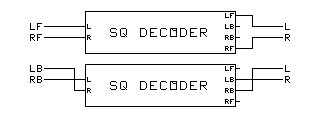 |
|
| lb = .7r − .7lj | rb = .7rj − .7l | |
| Rearrange the terms: | ||
| lb = − .7lj + .7r | rb = − .7l + .7rj | |
| Now substitute the encoding signals: | ||
| l = − .7LBj + .7RB | r = − .7LB + .7RBj | |
| Mix together the outputs of the front and back encoders: | ||
| l = LF − .7LBj + .7RB | r = RF − .7LB + .7RBj | |
| Compare with the original encoder equations: | ||
| l = LF − .7LBj + .7RB | r = RF − .7LB + .7RBj | |
| Notice that they are the same. | ||
The original SQ encoding setup above can be modified by adding a phase inverter switch. Do all of the following:
Features:
| The SQ diagonal split encoding equations are: | ||
| l = LF + .7LBj + .7RB | r = RF + .7LB + .7RBj | |
| The four SQ decoding equations are: | ||
| lf = l | rf = r | |
| lb = .7lj − .7r | rb = .7l − .7rj | |
| The SQ front channels can be used as is. Just substitute encoding signals: | ||
| l = LF | r = RF | |
| The SQ back channels are transposed as follows: Trade left for right at inputs and at outputs. | ||
| rb = .7rj − .7l | lb = .7r − .7lj | |
| Trade the equations: | 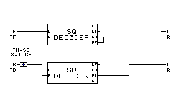 |
|
| lb = .7r − .7lj | rb = .7rj − .7l | |
| Rearrange the terms: | ||
| lb = − .7lj + .7r | rb = − .7l + .7rj | |
| Now substitute the encoding signals: | ||
| l = − .7LBj + .7RB | r = − .7LB + .7RBj | |
| Reverse the phase of the left back input signal: | ||
| l = .7LBj + .7RB | r = .7LB + .7RBj | |
| Mix together the outputs of the front and back encoders: | ||
| l = LF + .7LBj + .7RB | r = RF + .7LB + .7RBj | |
| Compare with the original encoder equations: | ||
| l = LF + .7LBj + .7RB | r = RF + .7LB + .7RBj | |
| They are the same. | ||
The original SQ encoding setup above can be modified by adding a different phase inverter switch. Do all of the following:
Features:
The Normal−Interior switch can be added. In the interior position, it randomizes phase between front and back for acroperiphony.
| The SQ forward−oriented encoding equations are: | ||
| l = LF + .7LB − .7RBj | r = RF − .7LBj + .7RB | |
| The four SQ decoding equations are: | ||
| lf = l | rf = r | |
| lb = .7lj − .7r | rb = .7l − .7rj | |
| The SQ front channels can be used as is. Just substitute encoding signals: | ||
| l = LF | r = RF | |
| The SQ back channels are transposed as follows: Trade left for right at inputs. | ||
| lb = .7rj − .7l | rb = .7r − .7lj | |
| Rearrange the terms: | 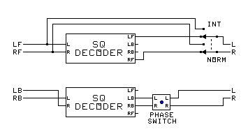 |
|
| lb = − .7l + .7rj | rb = − .7lj + .7r | |
| Now substitute the encoding signals: | ||
| l = − .7LB + .7RBj | r = − .7LBj + .7RB | |
| Reverse the phase of the left output signal: | ||
| l = .7LB − .7RBj | r = − .7LBj + .7RB | |
| Mix together the outputs of the front and back encoders: | ||
| l = LF + .7LB − .7RBj | r = RF − .7LBj + .7RB | |
| Compare with the original encoder equations: | ||
| l = LF + .7LB − .7RBj | r = RF − .7LBj + .7RB | |
| They are the same. | ||
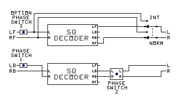 The Triple Encoder: 4−corners, diagonal split, and forward−oriented encoder:
The original SQ encoding setup above can be modified by adding both phase inverter switches. Do all of the following:
The equations above apply.
Features:
The Normal−Interior switch can be added. In the interior position, it randomizes phase between front and back for acroperiphony.
The backward−oriented encoding equations are as follows.
| The SQ backward−oriented encoding equations are: | ||
| l = − LF − .7LB − .7RBj | r = RF + .7LBj + .7RB | |
| The four SQ decoding equations are: | ||
| lf = l | rf = r | |
| lb = .7lj − .7r | rb = .7l − .7rj | |
| The SQ front channels get the left front phase inverted: | ||
| l = − LF | r = RF | |
| The SQ back channels are transposed as follows: Trade left for right at inputs. | ||
| lb = .7rj − .7l | rb = .7r − .7lj | |
| Rearrange the terms: | ||
| lb = − .7l + .7rj | rb = − .7lj + .7r | |
| Now substitute the encoding signals: | ||
| l = − .7LB + .7RBj | r = − .7LBj + .7RB | |
| Reverse the phase of the left output signal: | ||
| l = .7LB − .7RBj | r = − .7LBj + .7RB | |
| Reverse the phase of the left back input signal: | ||
| l = − .7LB − .7RBj | r = .7LBj + .7RB | |
| Mix together the outputs of the front and back encoders: | ||
| l = − LF − .7LB − .7RBj | r = RF + .7LBj + .7RB | |
| Compare with the original encoder equations: | ||
| l = − LF − .7LB − .7RBj | r = RF + .7LBj + .7RB | |
| They are the same. | ||
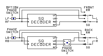 The Triple Encoder in a switched RM−SQ setup:
The Triple encoding setup above can be modified by adding RM−SQ switches. Do all of the following:
The equations above apply.
Features:
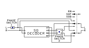 The Ultimate Encoder Pair (need at least two of these for full SQ):
The Switched encoding setup above can be modified by using a 3−position RM−SQF−SQB switch. Do all of the following:
The equations above apply.
Use table below to set the switches.
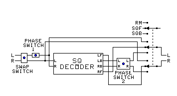 The Ultimate Encoder Pair with CircleSurround capability:
The Ultimate Encoder Pair above can be modified for CircleSurround by adding the swap switch. Do all of the following:
The equations above apply.
Setting the switches:
| SWITCH TABLE | |||||||
|---|---|---|---|---|---|---|---|
| OPERATION | CHANNELS | SWAP SWITCH |
PHASE SWITCH 1 |
PHASE SWITCH 2 |
MODE SWITCH |
PAN POT CONTROLS |
CROSS−FADE CONTROLS |
| Stereo Pass−Through | Stereo | Normal | Normal | − | RM | L − F − R | not used |
| Phased | Normal | Normal | − | SQF | L − F − R | not used | |
| RM Encoder | Front | Normal | Normal | − | RM | L − LF − F − RF − R | not used Use Flip Buses |
| Back | Normal | Reverse | − | RM | L −LB − B − RB − R | ||
| RM Acroperiphonic Encoder | Front | Normal | Normal | − | RM | L − LF − F − RF − R | F − C − B |
| Back | Normal | Reverse | − | SQF | L − LB − B − RB − R | ||
| SQ 4−Corners Encoder | Front | Normal | Normal | − | SQF | LF − F − RF | not used Use Flip Buses |
| Back | Normal | Normal | Normal | SQB | LB − B − RB | ||
| SQ Diagonal−Split Encoder | Front | Normal | Normal | − | SQF | LF − F − RF | F − Split − B |
| Back | Normal | Reverse | Normal | SQB | LB − F − RB | ||
| SQ Forward−Oriented Encoder | Front | Normal | Normal | − | SQF | LF − F − RF | F − Side − B |
| Back | Normal | Normal | Reverse | SQB | LB − F − RB | ||
| SQ Backward−Oriented Encoder | Front | Normal | Reverse | − | SQF | LF − B − RF | F − Side − B |
| Back | Normal | Reverse | Reverse | SQB | LB − B − RB | ||
| SQ Acroperiphonic Encoder | Front | Normal | Normal | − | RM | LF − F − RF | F − C − B |
| Back | Normal | Normal | Normal | SQB | LB − B − RB | ||
| UMX Basic Encoder | Left−Right | Normal | Normal | − | SQF | L − C − R | [L−R] − C − [F−B] |
| Front−Back | Normal | Normal | Reverse | SQB | F − C − B | ||
| RM 3D Front Encoder | Front | Normal | Normal | − | SQF | L − LF − F − RF − R | Horiz − Oblique − Vert |
| Down−Up | Normal | Normal | Reverse | SQB | N − NF − F − ZF − Z | ||
| RM 3D Back Encoder | Back | Normal | Reverse | − | SQF | L − LB − B − RB − R | Horiz − Oblique − Vert |
| Down−Up | Normal | Reverse | Reverse | SQB | N − NB − B − ZB − Z | ||
| CircleSurround Encoder | Front | Normal | Normal | − | SQF | LF − F − RF | F − Side − B |
| Back | Swap | Normal | Reverse | SQB | LB − F − RB | ||
Make the following changes:
Make the following changes:
Links: