Quadraphonic Arrangement
The normal way to place an image between two speakers is to "pan" the sound
between the speakers. This is a process of sending the sound to both speakers. The loudness
proportion between those speakers determines the position of the image of the sound heard
between the speakers. But this does not always work.
If the sound is placed between the left front (LF) and right front (RF)
speakers (and if the listener is facing to the front), level panning works quite well. As
the sound is panned from LF to RF, the listener hears it move from the LF speaker to the
RF speaker.
If the sound is placed between the left back (LB) and right back (RB)
speakers (and if the listener is facing to the front), level panning works somewhat well.
As the sound is panned from LB to RB, the listener hears it move from the LB speaker to
the RB speaker. But the motion is not as distinct as it is in front.
If the sound is placed between the left front (LF) and left back (LB)
speakers (and if the listener is facing to the front), level panning totally fails. The
listener's ears find the locations of the speakers instead of the panned sound positions.
If the sound is panned from LB to LF, the listener hears it suddenly jump from the LB
speaker to the LF speaker. The listener's head must turn to the left to correctly hear
the panned motion.
If the sound is placed between the right front (RF) and right back (RB)
speakers (and if the listener is facing to the front), level panning totally fails. The
listener's ears find the locations of the speakers instead of the panned sound positions.
If the sound is panned from RB to RF, the listener hears it suddenly jump from the RB
speaker to the RF speaker. The listener's head must turn to the right to correctly hear
the panned motion.
Clearly, this is not what was intended.
Quadraphonic Arrangement
| LOUD | ⊕ |
|
| SOFT |
| | |
|
| |
| | |
 |
| |
| | | |
| |
| | | |
| |
Left-Right Pan - WORKS
Front-Back Pan - FAILS
What happens here is based on how the human hearing system works and how it malfunctions
when presented with conflicting information.
When a sound source is perceived, the ears use the following information to determine the
perceived direction of the sound:
- Direction, order and timing of how the sound reaches each ear.
- Relative loudness of the sound reaching each ear.
- Reduction in high frequency sounds on the side of the head away from the sound.
- Phase shifting of sounds behind the hearer caused by the pinnae (earflaps).
- Multiple leading edges caused by convolutions in the pinnae from sounds approaching from
different elevation angles.
When one speaker is placed on each side of the listener, they combine to locate an image
of the sound:
- The sound reaches both ears at approximately the same time.
- Relative loudness of the sound reaching each ear is the primary locator of the sound
image.
- Reduction in high frequency sounds on the side of the head away from the sound does not
happen because speakers send sound to both sides of the head.
- Phase shifting of sounds behind the hearer occurs if the speakers are behind the
listener.
- Here there are no sounds approaching from above or below.
In this case, the panning artificially locates the sound between the speakers (the ⊕
symbol).
When two speakers are placed on the same side of the listener, conflicting information
reaches the ears:
- The sound from both speakers reaches the near ear first, followed by the far ear. Each
pair forms a different image.
- The sounds from both speakers are louder in the near ear than they are in the far
ear.
- Reduction in high frequency sounds happens in the far ear.
- Phase shifting of sounds behind the hearer may come from the speaker farther back.
- Here there are no sounds approaching from above or below.
In this case, the hearing system tries to make two different images from the conflicting
sounds.
Since they are the same sounds, the hearing system chooses the louder of the two (the
⊕ symbol), assuming the others are reflections.
If the sound is panned using levels from one speaker to the other, the hearing
system cogs (keeps the image at one speaker
until the other speaker becomes louder). Then the image jumps suddenly to the other
speaker.
A very few people claim to have trained their ears to hear the pan as a smooth motion.
But the page author does not see how they do it.
The page author has to turn his head to face the sound to hear the smooth panning.
Definition: Cog - To suddenly jump from one place to another.
Instead of panning smoothly, the sound cogs from speaker to speaker.
| LOUD | |
|
| LATE |
| | |
|
| |
| ⊕ | |
|
| |
| | | |
| |
| | | |
| |
Side Image Pan - WORKS
| LOUD | |
|
| |
| |
|
|
| |
| ⊕ |
|
|
| |
|
|
|
| |
| LOUD | |
|
| LATE; |
Front-Back Pan - WORKS
What happens here is based on how the human hearing system works and how it malfunctions
when presented with conflicting information.
One speaker is placed on each side of the listener, but the second one is delayed:
- The sound reaches the first ear earlier than the other ear.
- Relative loudness of the sound reaching each ear is secondary to timing.
- Reduction in high frequency sounds on the side of the head away from the sound can
also work here
- Phase shifting of sounds behind the hearer dies not occur here.
- The second speaker might need to be phase-reversed to the other speakers.
- Here there are no sounds approaching from above or below.
In this case, the panning artificially locates the sound to the early side (the ⊕
symbol).
The second speaker can be anywhere the other ear hears it first.
When two speakers are placed on the same side of the listener, a delayed secondary
speaker on the other side locates the image:
- The sound from both speakers reaches the near ear first, followed by the late speaker
at the far ear. The late signal coalesces the images.
- The sounds from both speakers are louder in the near ear than they are in the far
ear.
- Reduction in high frequency sounds happens in the far ear.
- Phase shifting of sounds behind the hearer may come from the speaker farther back.
- The late speaker might need to be phase-reversed to the other speakers.
- Here there are no sounds approaching from above or below.
In this case, the hearing system make a single image from the sounds.
Since they are the same sounds, the system makes them into one image (the ⊕
symbol).
Adjustment of the loudness of the loud sounds positions the image.
Dolby Surround uses this method to position sounds.

Quad 12 Diagram
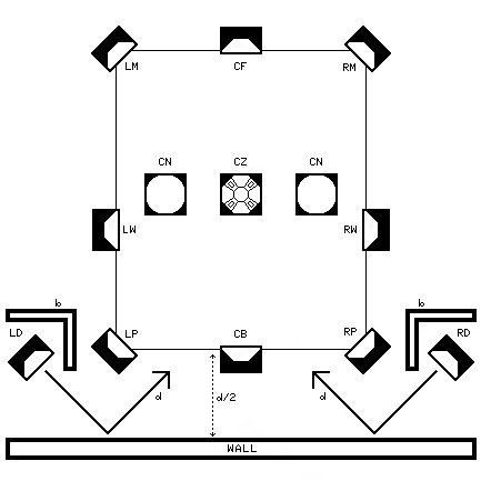
Supersurround Arrangement
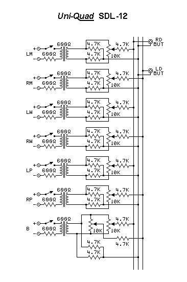
Delay collecting circuit
Using delay channels to remove the cogging:
This system has speakers to use with almost all systems:
The page author has Front, Main, Wing, Posterior, Back, Zenith, Nadir,
and Delay speakers.
Four more Top speakers can be added for Atmos.
For the delay speakers, any of the methods on the page
Creating Acoustic Audio Delays can be used.
The delay speakers will need to be at a lower volume than the
other speakers. They might also need either phase.
Quadraphonic uses the new delays to fix the side imaging problem:
- Most quadraphonic systems use LM = LF, RM = RF, LP = LB, and RP = RB.
- Use L-R for both D speakers, or use LD = RB and RD = LB.
- Dynaco Diamond uses CF = F, LW = L, RW = R, and RP = RB.
- Use L-R for both D speakers, or use LD = R and RD = L.
- Hex Tridee, Tetraphonic, and Spheround use LM = LF, RM = RF, LP = LB, RP = RB,
CZ = Z, and CN = N.
- Use L-R for both D speakers, or use LD = R and RD = L.
- For Discrete or CD-4, use LM = LF, RM = RF, LP = LB, and RP = RB.
- Use LF+RF+LB+RB for both D speakers.
Dolby surround can be used as is. It provides the needed delays:
- Dolby Surround and Pro Logic I use CF = C*, LM = L, RM = R, LP = LS, and RP = RS.
No extra delay system is needed.
- Dolby Pro Logic II uses CF = C*, LM = LM, RM = RM, LP = LS, and RP = RS.
No extra delay system is needed.
- Dolby Surround Tridee uses CF = C*, LM = L, RM = R, LP = LS, RP = RS,
CZ = Z, and CN = N.
No extra delay system is needed.
* - Many units have no center channel C and matrix it into the
L and R speakers.
Dolby Digital needs the new delays to fix the side imaging:
- Dolby 5.1 uses CF = C, LM = LF, RM = RF, LP = LS and RP = RS.
Use LD = CF+RM+RP and RD = CF+LM+LP.
- Dolby 7.1 uses CF = C, LM = LM, RM = RM, LW = LS, RW = RS
LP = LB, and RP = RB.
Use LD = CF+RM+RW+RP and RD = CF+LM+LW+LP.
Dolby Atmos needs the new delays but can use this speaker arrangement:
- Dolby 5.1.4 uses CF = C, LM = LM+LFT, RM = RM+LFT, LP = LS+LBT, RP = RS+RBT,
and CZ = LFT+RFT+LBT+RBT.
Use LD = CF+RM+RS+RFT+RBT and RD = CF+LM+LS+LFT+LBT.
- Dolby 7.1.4 uses CF = C, LM = LM+LFT, RM = RM+LFT, LW = LS, RW = RS
LP = LB+LBT, RP = RB+RBT, and CZ = LFT+RFT+LBT+RBT.
Use LD = CF+RM+RS+RB+RFT+RBT and RD = CF+LM+LS+LB+LFT+LBT.
Dolby Atmos with 4 extra speakers still needs the new delays:
- Dolby 5.1.4 uses CF = C, LM = LM, RM = RM, LP = LS, and RP = RS.
Also uses new speakers LFT, LBT, RFT, and RBT placed above LM, LP, RM, and RP.
Use LD = CF+RW+RP+RFT+RBT and RD = CF+LW+LP+LFT+LBT.
- Dolby 7.1.4 uses CF = C, LM = LM, RM = RM, LW = LS, RW = RS LP = LB, and RP = RB.
Also uses new speakers LFT, LBT, RFT, and RBT.
Use LD = CF+RM+RW+RP+RFT+RBT and RD = CF+LM+LW+LP+LFT+LBT.
Build a collector circuit to get signals from speakers for the delay channels.
- The delay channels use acoustic delays to fix the cogging problem.
- This circuit converts speaker-level signals to line level to feed
the delay amplifiers.
- Left speakers feed the right delay amp.
- Right speakers feed the left delay amp.
- It can have as many inputs as you need (3 are shown for each
side plus the special R-L circuit).
- It mixes the inputs together to make the needed signal.
- Each control can be set to give a positive or negative polarity.
- The switches allow changing setups for different surround systems.
- The special circuit at the bottom of the diagram allows adding a back
signal to both delay speakers.
Using the collector circuit.
- Use this acoustic audio delays page to
make the delays.
- Connect the speaker outputs of the channel amplifiers to the inputs of
the collector.
- Each control can be set to give a level at a positive or negative
polarity. Centered is off.
- Turn the speakers on one at a time and adjust the channel cross
level/phase to make the channel image correct.
- Turn the amplifier gain as low as it can go and still work. Both
amplifiers should have the same gain.
- Test the channels when all speakers on one side are working.
Cogging indicates improper adjustment.
- Use the switches to set up different surround systems.
- The sounds from the delay speakers should not be noticeable at normal
levels.