DOUBLE-BALL GULFSTREAM II
What is this? It was a project I did partly for a college class and partly for the pinball
arcade I worked for to put myself through college. The pinball machine makers had stopped
making the most popular kind of machine we had in the arcade (games where more than one ball
could be in play simultaneously), and we wanted another one. So I made one out of an old
machine.
This started as an independent laboratory project in a digital logic class in the fall of
1977. The assignment was to design something using a state machine. A state machine is a
device using a set of flip-flops and combinatory logic to determine the next state. I wanted
to see if I could design a multiple-ball pinball, so I decided on the following rules of the
game (using the Williams "Space Mission" pinball as a sample layout):
- The machine has two kick-out holes and the normal outhole at the bottom.
- If both balls are in the outhole, the ball in play ends.
- If one ball is in play and one is in the outhole or a kick-out hole, nothing occurs.
- If a ball enters a kick-out hole and one is in the outhole, a ball moves to the shooter.
- If one ball is in a kick-out hole and one enters the outhole, the ball in play ends
- If both balls are in kick-out holes, the indicated score is given and both balls eject.
- If a tilt occurs, the ball in play ends. The machine pauses until both balls are dead.
- If both balls are in kick-out holes during a tilt, both balls eject without any score.
I used the following assignment equations to determine the combinatory logic:
- Left, Right, Second, Out, Game, and Tilt are input switches.
- Eject, 2ndHd, and OutHd are flip-flops (they are on both sides of their equations).
- Eject := Home & Left & Right | ~ Done & Eject
- 2ndHd := (Home & Game & (Left | Right) & Out
| ~ Done & 2ndHd) ~ OutHd
- OutHd := Home & Game & (Left | Right | Out) & Second
| ~ Done & OutHd & | Tilt & 2ndHd &
- Home := ~ (Eject | 2ndHd | OutHd)
- Done := DELAY(~ Home)
Where "~" is a logical NOT, "&" is a logical AND, and
"|" is a logical or.
Note that "~" has precedence over "&", which has precedence
over "|".
The variables Home and Done are a simulation of the mechanical score motor in the pinball
machine. DELAY is a logical delay that turns on a short time after its input goes true,
simulating the rotation of the score motor.
In the real machine, Eject turns off the Left and Right switches by ejecting the balls, and
2ndHd and OutHd turn off the Out switch by ejecting that ball. Once the out switch goes off,
gravity moves any ball on the Second switch to the Out switch. I did not simulate this, but
changed the switches by hand. I used a pushbutton to assert Done, since I had to move these
switches first. Lights showed me the state of each variable.
Game indicates that the game is not over. Tilt indicates that the machine has been tilted.
Doing the logic:
| | SECOND
=
False |
SECOND
=
True |
SECOND
=
False | |
LEFT
=
False | nil |
nil | OutHd |
nil | RIGHT
=
False |
LEFT
=
True |
nil
| OutHd |
c-h |
2ndHd
† |
Eject
‡ | c-h |
c-h | c-h |
RIGHT
=
True |
LEFT
=
False | nil |
OutHd | c-h |
2ndHd
† |
| | OUT
=
False |
OUT
=
True | |
The logic table at right shows which flip-flop (if any) is set by the switch
combinations:
- The red and green boxes are the inputs to the table. Select the row and column
from the values set on the switches.
- The white, gray, and blue boxes are the outputs from the table. The row and
column selected chooses which output the logic selects.
- nil - No action occurs.
- c-h - This combination "can't happen" because there are only two
balls.
- OutHd - the ball in play ends.
- 2ndHd - A ball moves from the outhole to the shooter.
† - If a tilt has happened, the ball in play ends instead.
- Eject - The indicated score is given and both balls eject.
‡ - If a tilt has happened, the score is not given.
This was a very interesting exercise in how to make a multiple-ball pinball machine. At the
time, I thought that this was as far as it would go. I had a thought of building a miniature
pinball machine but that was just a dream.
The next step was to convert it into switch and relay logic.
 In 1978, we had an older machine, a Williams "Gulfstream" that pulled in at most
75 cents a day. We put it up for sale, and nobody wanted it. So I suggested trying to convert
it to multiple-ball play. Since this seemed better than any other option, the owners agreed.
This advanced my theoretical project to practicality.
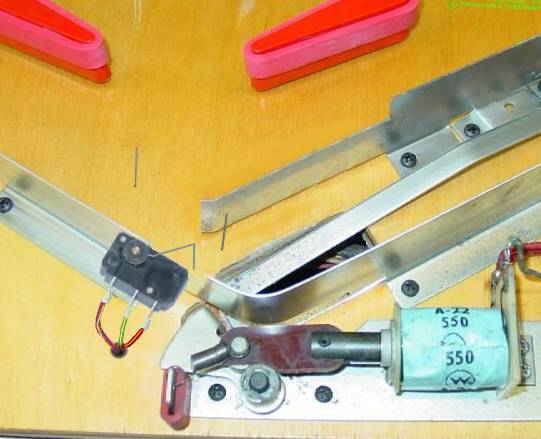
First I designed the 2nd Ball Switch. I tried different positions of the 2nd Ball Switch
(held in place with tape) until I got it to work reliably. I temporarily connected the 2nd
Ball Switch in series with the Outhole Switch and played the machine normally with two balls in
the ball trough. It put only one ball on the playfield at a time. I noted when and how it
malfunctioned and adjusted the switch and other parts until it worked smoothly and reliably.
I left it that way when I was not working on it so errors it caused when others played it
would be recorded on the mistake (trouble) report.
Then I fastened it in permanently. The image here is a photo of an actual Gulfstream ball
return with material edited (with an image editor) into the image for the 2nd Ball Switch,
the extended ball guide, and two vertical pins to keep the ball from bounding where it
shouldn't. This image was done entirely from memory.
That pin off by itself was there to keep a fast ball from bouncing clear through the 2nd
Ball switch and the outhole and partway up the ball return. This caused a fast drain to turn
into a free ball by not activating the 2nd ball switch long enough to pull in the relay.
Then I developed the relay logic from the logic table above.
| Logic Table: | Out | Second |
Left | Right |
OutHd | 2ndHd | Eject |
Pinball
Part: | Outhole
Switch | 2nd Ball
Switch |
Left Hole
Switch | Right Hole
Switch |
Outhole
Relay | 2nd Ball
Relay | Kick Out
Relay |
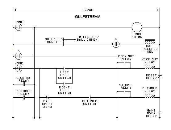 Here is the original way the Gulfstream was wired.
- The score motor handles all functions of the pinball machine other than single digit
scores and simple switching (such as flippers, or hitting a target to light another
target).
- The score motor has several named cams that are activated in the following order:
P, 1, P, 2, P, 3, P, 4, P, 5, Home
The P cam has 5 pulse lobes for scores that are multiples of 5.
- The circled contacts are score motor contacts. They are shown with the score motor in the
home (stopped) position.
- Only the circuits having to do with the parts used for the double-ball modification are
shown. They use existing switches on the Home, 4, and 5 cams on the score motor.
- The ball release solenoid sends the ball to the shooter for the player to shoot it.
- The two ejector holes on the playfield (LEFT HOLE AND RIGHT HOLE) give 500 points (and
the special, if lit) and eject the ball.
- The Ball Count Zero Switch opens when the last ball in the game has ended.
- The Kick Out Relay operates the ejector holes and gives the score for them.
- The Outhole is where the ball goes when you lose it.
- The Outhole switch is closed when the ball is in the outhole.
- The Outhole Relay ends the ball in play and either advances to the next ball or ends
the game if the Ball Count Zero switch opens because no balls are left.
- Many other parts of the pinball machine are not shown here. The real schematic would
fill several computer screens.
Each score motor function uses a relay, and usually works in the following way:
- Some event (usually on the playfield) activates a relay, which locks itself on.
- Contacts on the relay start the score motor.
- The score motor Home switch opens the circuit that enables the relays, so two functions
are not attempted at the same time.
- All scoring or other functions the relay causes are completed.
- If the ball is in a hole, the 4 cam kicks it out.
- The 5 cam unlocks the relay, letting it shut off.
- The Home switch stops the score motor and enables all of the relays again.
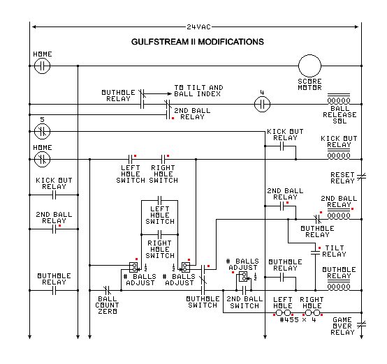 The schematic on the right is similar to what I originally sketched, except the tilt relay
connections and the flasher bulbs were not there. After I had the diagram, I made the
following changes. Here are some details of the modification as I remember them:
- Any item with a red dot is an added item or a part added to an item.
- The "# BALLS ADJUST" triple plug can return the game to its original operation
(the second ball must be removed too).
- I removed the 10-Cent Relay (not in use because games were 25 cents then) and used it for
the 2nd Ball Relay (mounted next to the Outhole Relay).
- In the diagram at right, a red dot means that the item was added.
- I had to add leaves to the switch stacks for the Outhole Relay and the Outhole Switch.
That was easy with a switch stack kit.
- The ball capture holes were the two ejector holes on the playfield (LEFT HOLE AND RIGHT
HOLE). I had to add leaves to the switch stacks for the ejector holes.
- I wired the 2nd Ball Relay into the outhole and kick-out circuits to implement the
logic table.
- The machine does nothing about the position of the balls until it knows where all of the
balls are at the same time.
- The difference between a ball already being in the outhole and a ball draining from the
playfield is detected by whether the Outhole switch or the 2nd Ball Switch is activated
when the machine detects that all of the balls are in known positions.
- Note that by the time the draining ball gets to the outhole, the score motor has already
started rotating (from the 2nd Ball Switch) and the switches are disabled until the motor
finishes rotating. Normally the ball reaches the outhole before the Ball Return Solenoid
is activated. If it has not, the score motor will rotate again when it does and kick the
ball out.
- When one ball went into either eject hole, it kept it and put the other ball (if not in
play) at the shooter without giving the 500 points or the special (if lit).
- When both balls were in eject holes, it gave the 500 points (and the special, if lit)
and ejected both balls simultaneously.
- I put a Roman numeral II inside the M in the word Gulfstream on the backglass (see photo
at top of page).
- I made a new instructions card for the panel next to the shooter (Similar card simulated
from memory at right).
A FEW MINOR SETBACKS:
INSTRUCTIONS
- MAKING THE WORD S-P-E-C-I-A-L LIGHTS BOTTOM ROLLOVERS
TO SCORE 1 REPLAY.
- MAKING EITHER EJECT HOLE CAPTURES THE BALL AND GIVES
A FREE BALL AT THE SHOOTER.
→
- MAKING BOTH EJECT HOLES WHEN FLASHING EJECTS BOTH
BALLS AND SCORES INDICATED VALUE
- MAKING 3 IN LINE LIGHTS EJECT HOLE SPECIALS TO SCORE 1
EXTRA BALL WHEN BOTH BALLS EJECT.
- MAKING 4 CORNERS SCORES 1 REPLAY.
- MATCHING LAST 2 DIGITS ON SCORE REELS TO LIGHTED NUMBER
ON BACKGLASS WHEN GAME IS OVER GIVES 1 REPLAY.
|
After I initially turned on the machine for people to play, some bugs showed up. The
following were changes I made to fix them:
- If the machine was tilted and a ball went into one of the eject holes, it wrongly gave a
free ball at the shooter and canceled the tilt. I added the switch and connections to
the Tilt Relay to fix this. After this change, if this happened while the machine was tilted,
it did not give the second ball. Instead, it waited until both balls were in known places
and at least one was in the outhole before resuming play.
- I kept having people report the ball was stuck. I had to show them that another ball
appeared at the shooter. I added the flashing lights under the ejector holes to call
attention to the instructions. The four #455 bulbs were mounted two under each kick-out
hole. In series, they add to 24 volts. They flash when capturing the second ball would
cause both to be ejected. This is based solely on what I remembered. I have no documents
I kept to show this.
- A fast ball sometimes bounced clear through the 2nd Ball Switch and the outhole and
partway up the ball return. This cause a fast drain to turn into a free ball by not
activating the 2nd Ball Switch long enough to pull in the relay. I added that pin off
by itself to deflect the fast ball away from the outhole.
- One player was able to continuously win enough games to play on one quarter all
afternoon. I made the following changes to make it harder to win games:
- I made some of the specials give extra balls instead of replays.
- I adjusted the side lanes to their widest settings to make it easier to drain a
ball.
- I modified the high score replay so each replay score would work only once in a
game.
- I adjusted the maximum number of balls the ball counter could hold to be 6.
- I adjusted the maximum number of credits the credit reel could hold to be 5 (as we
did for all machines in the arcade).
- I adjusted the tilt bob to be very sensitive (as we did for all machines in the
arcade).
- I made certain events that would have not ordinarily clear sequences clear the
lit bumpers, S-P-E-C-I-A-L and 3 X 3 square sequences. But I can't remember what I
used to do which. Possibly the On Bumpers targets cleared the 3X3 square, the 1000
outlanes cleared the S-P-E-C-I-A-L sequence, and the Spot target turned the bumpers
off.
I used an image editor to make files from the info on my crude notes on 39-year-old
yellowed notebook paper. The results are the two schematic images above.
I am not sure of some of the relay names. I had two sets of notes with different names for
some of the relays.
Since the 2nd Ball Relay is new, I showed all connections to it. I had to use 4 pages
of my notes to find all of them.
For other relays, I showed only parts that had connection changes or parts needed to
complete a shown circuit.
The photo at the top of the page is a cropped version of the only photo I have of the
machine. I cropped it because most of the rest of the photo has people in it, hiding most
of the rest of the machine. I cropped them off because I don't have permission to use
their images.
After the modifications, "Gulfstream II" became our #3 machine in daily take
in quarters. Only the Bally "Fireball" and the Gottleib "Solar City"
took in more quarters per day.
EPILOG
This machine started the multiball craze. Before 1978, I knew of only a few machines made
by Bally that could do multiple-ball play ("Fireball", "Nip-It",
"Gator", and a few others) and they had a lot of relays to keep track of multiple
balls. I did it with one added relay. After our arcade closed, my multiple-ball design was
copied into the Williams "Flight 2000" and "Firepower" pinball machines,
but with computer program logic instead of relays.
Note that the terms LOCK and MULTIBALL were coined by Williams when they built those
machines. My instructions included the terms CAPTURE and FREE BALL instead.
I do not have the Gulfstream or the paperwork that came with it. The papers were kept in
the machine. The arcade company I worked for went out of business rather suddenly in 1979
and all of the machines they owned disappeared then. But I have recently seen photos
of the Gulfstream II online.
APPENDIX
How the repurposed circuits work:
- If both balls are in the outhole, the Outhole Relay operates, ending the ball in play.
- If both balls are free on the playfield and one enters the outhole, nothing happens.
- If both balls are free on the playfield and one enters a kick-out hole, nothing happens.
- If one ball is in the outhole and one enters a kick-out hole, the 2nd Ball Relay moves
the ball in the outhole to the shooter.
- If one ball is in a kick-out hole and one enters the outhole, the Outhole Relay operates
as above.
- When both balls are in kick-out holes, the Kick-Out Relay gives the indicated score and
ejects both balls.
- When one ball is in the outhole and one enters a kick-out hole during a tilt, the Outhole
Relay operates.
- If both balls are in kick-out holes during a tilt, the Kick-Out Relay ejects both balls
without any score.
- Whenever a ball is in either kick-out hole, the flashing lights light up the kick-out
holes.
Gulfstream photos:
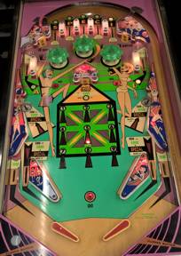
Gulfstream
Playfield *
|
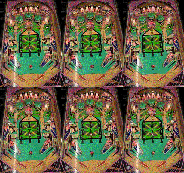
Gulfstream II with Captured Ball
and Flashing Kick-Out Lights †
|
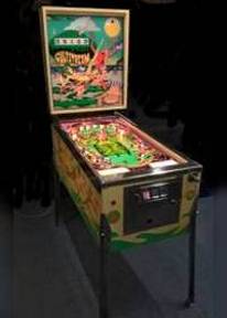
A Gulfstream Machine
(Background edited out) *
|
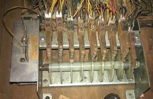
Williams Pinball
Score Motor
|
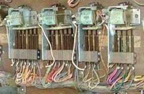
Williams
Pinball Relays
|
* Thanks to Mark Squires for the images
† My edited version of image at left


 In 1978, we had an older machine, a Williams "Gulfstream" that pulled in at most
75 cents a day. We put it up for sale, and nobody wanted it. So I suggested trying to convert
it to multiple-ball play. Since this seemed better than any other option, the owners agreed.
This advanced my theoretical project to practicality.
 Here is the original way the Gulfstream was wired.
 The schematic on the right is similar to what I originally sketched, except the tilt relay
connections and the flasher bulbs were not there. After I had the diagram, I made the
following changes. Here are some details of the modification as I remember them:


