Permissive Left for Yellow Trap Problem with no Left Turn Phase
No Relays
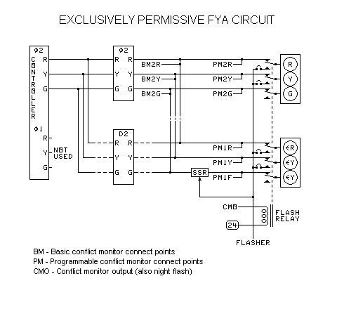
This is used where the flashing yellow arrow is needed to prevent yellow trap from an opposing left turn phase or a pre-emption.
| Basic Monitor | Programmable Monitor |
|||||
|---|---|---|---|---|---|---|
| Lamp | Con- flict | Dark Face | Burn Out |
Con- flict | Dark Face | Burn Out |
| Φ2 R | Yes | Yes | No | Yes | Yes | No* |
| Φ2 Y | Yes | Yes | No | Yes | Yes | No* |
| Φ2 G | Yes | Yes | No | Yes | Yes | No* |
| D2 R | Yes | Yes | No | Yes | Yes | No* |
| D2 Y | Yes | Yes | No | Yes | Yes | No* |
| D2 FY | Yes | Yes | No | Yes | Yes | No* |
* The second load switch (D2) shown can be used to improve conflict monitoring, making these entries Yes.
The phase D2 is the left turn that turns across the phase Φ2. This circuit derives it from Φ2. It does not exist in the controller.
| Sequence | ||||||
|---|---|---|---|---|---|---|
| Signal | 1 | 2 | 3 | 4 | 5 | 6 |
| Φ2 | R | G | Y | R | R | - |
| O2 | R | FY | Y | R | R | - |
| Other | R | R | R | R | OK | - |
SSR = Solid State Relay.
Protected/Permissive Left for Yellow Trap Problem with No Overlap Phase
Relays After the Load Switches
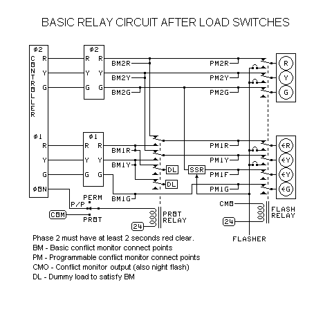
This is used where the flashing yellow arrow is needed to prevent yellow trap from an opposing left turn phase or a pre-emption.
| Basic Monitor | Programmable Monitor |
|||||
|---|---|---|---|---|---|---|
| Lamp | Con- flict | Dark Face | Burn Out |
Con- flict | Dark Face | Burn Out |
| Φ2 R | Yes | Yes | Yes | Yes | Yes | Yes |
| Φ2 Y | Yes | Yes | Yes | Yes | Yes | Yes |
| Φ2 G | Yes | Yes | Yes | Yes | Yes | Yes |
| Φ1 R | Yes | No | Yes | Yes | Yes | Yes |
| Φ1 Y | Yes | No | Yes | Yes | Yes | Yes |
| Φ1 FY | Yes | No | No | Yes | Yes | Yes |
| Φ1 G | Yes | No | Yes | Yes | Yes | Yes |
The phase Φ1 is the left turn that turns across the phase Φ2.
The dummy loads will not affect the conflict monitor's ability to detect lamp burnout if there are red clearance periods on all affected phases, because:
- There will then be sufficient periods of time when the real lamp is connected and the load switch is on, and also when it is off.
- There will also be sufficient periods when any extra lamp is disconnected and the load switch is on, and also when it is off.
The dummy loads prevent false tripping when no lamp is connected.
Dummy loads are not needed with the programmable monitors.
| Sequence | |||||||||
|---|---|---|---|---|---|---|---|---|---|
| Lead Left | 1 | 2 | 3 | 4 | 5 | 6 | 7 | 8 | 9 |
| Φ1 | R | G | Y | R | FY | Y | R | R | - |
| Φ2 | R | R | R | R | G | Y | R | R | - |
| Other | R | R | R | R | R | R | R | OK | - |
| Lag Left | 1 | 2 | 3 | 4 | 5 | 6 | 7 | 8 | 9 |
| Φ1 | R | FY | Y | R | G | Y | R | R | - |
| Φ2 | R | G | Y | R | R | R | R | R | - |
| Other | R | R | R | R | R | R | R | OK | - |
Protects one left-turn and opposing straight-ahead pair from yellow trap.
Protected/Permissive Left for Yellow Trap Problem with No Overlap Phase
Relays Before the Load Switches
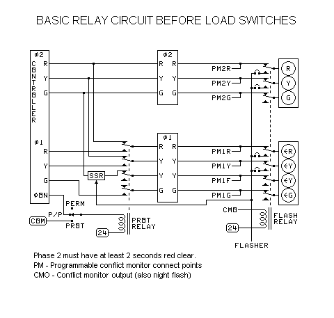
This is used where the flashing yellow arrow is needed to prevent yellow trap from an opposing left turn phase or a pre-emption.
| Basic Monitor | Programmable Monitor |
|||||
|---|---|---|---|---|---|---|
| Lamp | Con- flict | Dark Face | Burn Out |
Con- flict | Dark Face | Burn Out |
| Φ2 R | - | - | - | Yes | Yes | Yes |
| Φ2 Y | - | - | - | Yes | Yes | Yes |
| Φ2 G | - | - | - | Yes | Yes | Yes |
| Φ1 R | - | - | - | Yes | Yes | Yes |
| Φ1 Y | - | - | - | Yes | Yes | Yes |
| Φ1 FY | - | - | - | Yes | Yes | Yes |
| Φ1 G | - | - | - | Yes | Yes | Yes |
The phase Φ1 is the left turn that turns across the phase Φ2.
| Sequence | |||||||||
|---|---|---|---|---|---|---|---|---|---|
| Lead Left | 1 | 2 | 3 | 4 | 5 | 6 | 7 | 8 | 9 |
| Φ1 | R | G | Y | R | FY | Y | R | R | - |
| Φ2 | R | R | R | R | G | Y | R | R | - |
| Other | R | R | R | R | R | R | R | OK | - |
| Lag Left | 1 | 2 | 3 | 4 | 5 | 6 | 7 | 8 | 9 |
| Φ1 | R | FY | Y | R | G | Y | R | R | - |
| Φ2 | R | G | Y | R | R | R | R | R | - |
| Other | R | R | R | R | R | R | R | OK | - |
Protects one left-turn and opposing straight-ahead pair from yellow trap.
Protected/Permissive Left for Yellow Trap Problem with One Overlap Phase
Relays After the Load Switches
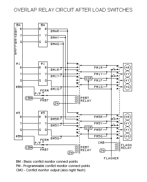
This is used where the flashing yellow arrow is needed to prevent yellow trap from an opposing left turn phase or a pre-emption.
Uses one overlap phase to control both left turn signals. This version does not have to stop the flashing yellow arrow movement before starting the green arrow.
| Basic Monitor | Programmable Monitor |
|||||
|---|---|---|---|---|---|---|
| Lamp | Con- flict | Dark Face | Burn Out |
Con- flict | Dark Face | Burn Out |
| Φ1,5 R | Yes | No | No | Yes | Yes | Yes |
| Φ1,5 Y | Yes | No | No | Yes | Yes | Yes |
| Φ1,5 FY | No | No | No | Yes | Yes | Yes |
| Φ1,5 G | Yes | No | No | Yes | Yes | Yes |
The phase Φ1 is the left turn that turns across the phase Φ2.
The phase Φ5 is the left turn that turns across the phase Φ6.
Overlap Phase OA is green whenever Φ1, Φ2, Φ5, or Φ6 is green.
Lamp and dark face checking is not possible with the basic monitor.
| Sequence | |||||||||||
|---|---|---|---|---|---|---|---|---|---|---|---|
| Lead Left | 1 | 2 | 3 | 4 | 5 | 6 | 7 | 8 | 9 | 10 | 11 |
| Φ1 | R | G | G | G | Y | R | FY | Y | R | R | - |
| Φ2 | R | R | R | R | R | R | G | Y | R | R | - |
| Φ5 | R | G | Y | R | FY | FY | FY | Y | R | R | - |
| Φ6 | R | R | R | R | G | G | G | Y | R | R | - |
| OA | R | G | G | G | G | G | G | Y | R | R | - |
| Other | R | R | R | R | R | R | R | R | R | OK | - |
| Lag Left | 1 | 2 | 3 | 4 | 5 | 6 | 7 | 8 | 9 | 10 | 11 |
| Φ1 | R | FY | FY | FY | FY | FY | G | Y | R | R | - |
| Φ2 | R | G | G | G | Y | R | R | R | R | R | - |
| Φ5 | R | FY | FY | FY | G | G | G | Y | R | R | - |
| Φ6 | R | G | Y | R | R | R | R | R | R | R | - |
| OA | R | G | G | G | G | G | G | Y | R | R | - |
| Other | R | R | R | R | R | R | R | R | R | OK | - |
| Lead- Lag | 1 | 2 | 3 | 4 | 5 | 6 | 7 | 8 | 9 | 10 | 11 |
| Φ1 | R | G | Y | R | FY | FY | FY | Y | R | R | - |
| Φ2 | R | R | R | R | G | G | G | Y | R | R | - |
| Φ5 | R | FY | FY | FY | FY | FY | G | Y | R | R | - |
| Φ6 | R | G | G | G | Y | R | R | R | R | R | - |
| OA | R | G | G | G | G | G | G | Y | R | R | - |
| Other | R | R | R | R | R | R | R | R | R | OK | - |
Protects two left-turn and straight-ahead pairs on the same street from yellow trap.
Protected/Permissive Left for Yellow Trap Problem with One Overlap Phase
Relays Before the Load Switches
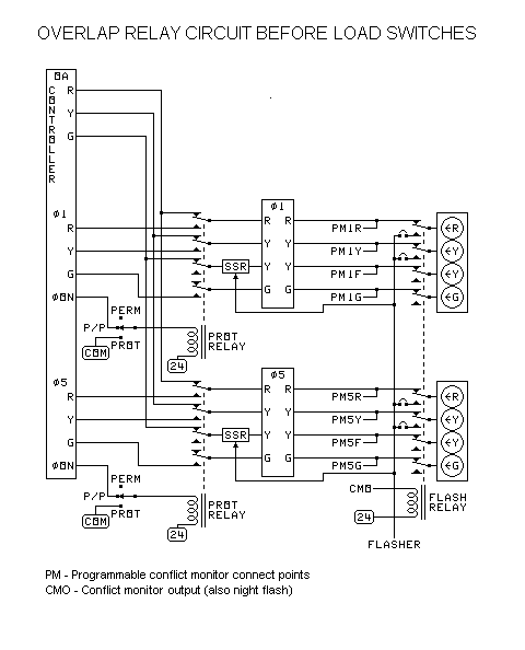
This is used where the flashing yellow arrow is needed to prevent yellow trap from an opposing left turn phase or a pre-emption.
Uses one overlap phase to control both left turn signals. This version does not have to stop the flashing yellow arrow movement before starting the green arrow.
| Basic Monitor | Programmable Monitor |
|||||
|---|---|---|---|---|---|---|
| Lamp | Con- flict | Dark Face | Burn Out |
Con- flict | Dark Face | Burn Out |
| Φ1,5 R | - | - | - | Yes | Yes | Yes |
| Φ1,5 Y | - | - | Yes | Yes | Yes | |
| Φ1,5 FY | - | - | - | Yes | Yes | Yes |
| Φ1,5 G | - | - | - | Yes | Yes | Yes |
The phase Φ1 is the left turn that turns across the phase Φ2.
The phase Φ5 is the left turn that turns across the phase Φ6.
Overlap Phase OA is green whenever Φ1, Φ2, Φ5, or Φ6 is green.
| Sequence | |||||||||||
|---|---|---|---|---|---|---|---|---|---|---|---|
| Lead Left | 1 | 2 | 3 | 4 | 5 | 6 | 7 | 8 | 9 | 10 | 11 |
| Φ1 | R | G | G | G | Y | R | FY | Y | R | R | - |
| Φ2 | R | R | R | R | R | R | G | Y | R | R | - |
| Φ5 | R | G | Y | R | FY | FY | FY | Y | R | R | - |
| Φ6 | R | R | R | R | G | G | G | Y | R | R | - |
| OA | R | G | G | G | G | G | G | Y | R | R | - |
| Other | R | R | R | R | R | R | R | R | R | OK | - |
| Lag Left | 1 | 2 | 3 | 4 | 5 | 6 | 7 | 8 | 9 | 10 | 11 |
| Φ1 | R | FY | FY | FY | FY | FY | G | Y | R | R | - |
| Φ2 | R | G | G | G | Y | R | R | R | R | R | - |
| Φ5 | R | FY | FY | FY | G | G | G | Y | R | R | - |
| Φ6 | R | G | Y | R | R | R | R | R | R | R | - |
| OA | R | G | G | G | G | G | G | Y | R | R | - |
| Other | R | R | R | R | R | R | R | R | R | OK | - |
| Lead- Lag | 1 | 2 | 3 | 4 | 5 | 6 | 7 | 8 | 9 | 10 | 11 |
| Φ1 | R | G | Y | R | FY | FY | FY | Y | R | R | - |
| Φ2 | R | R | R | R | G | G | G | Y | R | R | - |
| Φ5 | R | FY | FY | FY | FY | FY | G | Y | R | R | - |
| Φ6 | R | G | G | G | Y | R | R | R | R | R | - |
| OA | R | G | G | G | G | G | G | Y | R | R | - |
| Other | R | R | R | R | R | R | R | R | R | OK | - |
Protects two left-turn and straight-ahead pairs on the same street from yellow trap.


