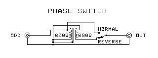
SURROUND ENCODER PHASE SWITCH
 You will need the following:
- One 600 ohm to 600 ohm audio isolation transformer
- 1 small plastic box to mount the parts in.
- Two RCA jacks.
- One single-pole double-throw switch
- Either a ready-made grid PC board or some solder-lug terminal strips to mount parts on.
- Wire
Assembly Instructions:
- Find the marking that indicates the primary winding (usually a blue or black band).
- Mark the hot phase of each winding with a magic marker such that it can be seen after the transformers are
mounted. If you can't determine phase, mark the diagonally opposite terminals of both transformers. IMPORTANT! Make
sure each mark is on a different winding (use an ohmmeter).
- Make holes in the box for the jacks and the screws to mount the terminal strips, PC board, or transformers.
- If using terminal strips, mount them to the box. If using a PC board, make mounting holes, but do not mount it to
the box until told to. Make sure the transformers will not obstruct the mounting holes.
- Mount the transformers to the PC board or terminal strips. Be sure the transformer is supported by its mounting
lugs, not the connections. Do not mount the PC board yet.
- Connect each transformer lead to a different circuit board pad or solder lug.
- Decide on a color code for hot, and ground. Wire all plugs using the same color code.
- Label one jack as ODD and the other as OUT.
- Connect the ODD jack to the primary transformer winding, connecting the hot to the hot phase, and the ground to
the other end of the winding.
- Connect the hot terminal of the OUT jack to the common pole of the switch.
- Connect the ground terminals of the two jacks together.
- Connect the hot terminal of the ODD jack to the switch contact connected in the Normal position of the switch.
- Connect the hot terminal of the transformer secondary to the ground of the ODD jack.
- Connect the ground terminal of the transformer secondary to the switch contact connected in the Reversed position
of the switch.
- If using a circuit board, mount it now.
- Finish assembling the box.
Testing
- Connect the phase switch in the left channel of the leads from your sound source to your regular RM or Dolby
Surround decoder.
- The right channel should have its normal connections.
- Set the switch to Normal.
- Play a surround sound recording through the switch and the Dolby Surround system.
- While the recording is playing, flip the switch to Reverse. This should cause the front and back images to
trade places in the speakers.
- If the image does not change position, the transformer is wired wrong. Reverse the connections to the secondary
winding.
Do not link to this page, but to the parent page. If you followed someone else's link to
this page, go HOME to find the article on Surround Sound Mixing. Then
complain to the jerk who put this page in a link table.
 You will need the following:
 You will need the following: