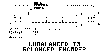
SURROUND ENCODER CABLE (unbalanced-balanced)
CONSTRUCTING PATCH CORD A
 Cut two equal lengths of mic cable sufficiently long to easily reach from your SUB OUT connectors to your
ENCODER RETURN connectors. Leave a foot or two extra to allow for putting on the connectors, extra slack, and
eventual repairs.
Cut two equal lengths of mic cable sufficiently long to easily reach from your SUB OUT connectors to your
ENCODER RETURN connectors. Leave a foot or two extra to allow for putting on the connectors, extra slack, and
eventual repairs.- Connect a balanced-line plug that fits your ENCODER RETURN connectors to one end of each piece of cable.
Solder the wires to the terminals in normal balanced-line fashion. Be sure to connect the shields. Remember which
colored wire goes to the hot terminal, and which goes to the cold.
- Mark one of the connectors you just put on as LEFT ENCODER RETURN. Mark the other as RIGHT ENCODER RETURN.
- Connect a plug that fits your SUB OUT connectors to the other end of only the RIGHT cable. Solder the hot
wire to the live terminal, and solder the cold wire to the ground terminal. Do not connect the shield at this
end.
- Mark this connector as RIGHT SUB OUT.
- Connect a plug that fits your SUB OUT connectors to the other end of the LEFT cable (this is the tricky
part). Solder the cold wire to the live terminal, and solder the hot wire to the ground terminal. Do not
connect the shield at this end.
- Mark the connector you just put on as LEFT SUB OUT.
- Placing the RETURN connectors together at one end, and the SUB OUT connectors at the other end, bundle the
cables together with cable ties or string.
Click BACK to return to the instructions.
Do not link to this page, but to the parent page. If you followed someone else's link to this page, go
HOME to find the article on Mixing Surround Sound With Your Mixer. Then complain loud and
long to the jerk who put this page in a link table.
 Cut two equal lengths of mic cable sufficiently long to easily reach from your SUB OUT connectors to your
ENCODER RETURN connectors. Leave a foot or two extra to allow for putting on the connectors, extra slack, and
eventual repairs.
 Cut two equal lengths of mic cable sufficiently long to easily reach from your SUB OUT connectors to your
ENCODER RETURN connectors. Leave a foot or two extra to allow for putting on the connectors, extra slack, and
eventual repairs.