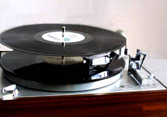
IMPROVE A COLLARO TSC-640 CONQUEST
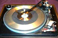
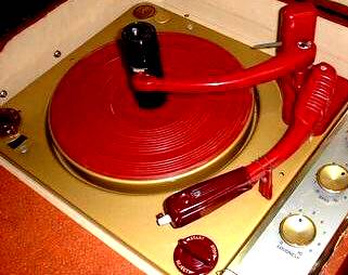
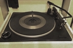
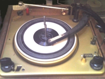
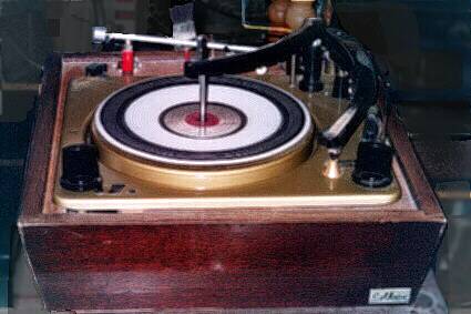
The author's Collaro playing a mixed-speed stack
You can make your Collaro Conquest work like mine.
The Collaro TSC-640 is a very useful and durable record changer.
It was factory-made with these features:
- A mechanism that has very few failures over its long life
- It has only two parts that need periodic maintenance (two rubber drive wheels)
- A velocity trip mechanism that works at low tracking forces without modification
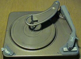
- Automatic sensing of record size (arm touches the stack, as seen at right)
- Automatic indexing of odd record sizes from 12-inch to 6.25-inch ♠
- Automatic pyramid-arranged record size intermix (larger must be below
smaller) ♠
- Automatic shutoff after the last record
- Automatic stylus protection. If it is started with no record, it shuts itself off.
- Manual start and stop
- Trip-defeat manual start (not in the instructions)
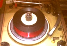
- Record thickness sensing changer spindle (next image below)
- Jam-proof mechanism
♠ Not included in Magnavox instructions.
The Collaro Conquest is very trouble-free. These are the very few times the page author
has had to repair his 1960 Collaro:
- The mica blades for the muting switch were broken when he got it used in 1970.
Collaro spindle
- He replaced them with plastic guitar picks.
- The original rubber drive wheels were replaced with synthetic rubber ones in the
mid 1970s.
- Synthetics don't deteriorate the way the original ones did.
- He is using Caig CaiKleen RBR rubber cleaner followed by Isopropyl alcohol.
- These keep the new wheels soft and operational.
- The spring clips on both of the control knobs broke at different times.
- He made replacements from spring steel straps.
- The spring for the arm raising lever broke.
- He made a replacement using a spring bender on a similar purchased spring.
You can add these features:
Take-away overarm
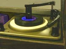
Overarm used as in instructions
- Use trip-defeat manual start (no modification)
- A quieter running motor and turntable.
- Take-away Overarm (right), an alternative to the large hole spindle use as in the
instructions (lower right).
- Increase arm travel for 4-inch records
- Add to auto record size range of TSC-640/200 for 6-inch records
- Make dual-range record size index for other TSC-640 models
- Improved arm bearings
- Antiskate
- Add Cue Control to early TSC-640 models
- Fit a magnetic cartridge to TSC-640/200
- Use repeating discs with all TSC-640 models (no modification)
- Add Turntable Stop to early TSC-640 models
- Add Autospeed to early TSC-640 models
- Add a Pitch Control to early TSC-640 models
The photo at the top of this page is the page author's Collaro with all of the
modifications playing a mixed-speed stack.
The page author owns two TSC-640/200 changers that were identical when he got them.
- He modified one of then to make the pictured record changer above.
- The other was originally bought for possibly needed spare parts and is
still in its original state inside a Magnavox Belvedere console.
PE-2038-B
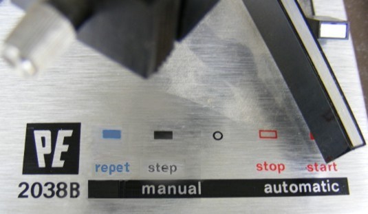
PE-2038-B Control
Collaro PH-1252
Dual 1004
The main reason the author made this instead of buying a changer made for his purposes
is:
NOBODY EVER MADE SUCH A RECORD CHANGER.
He could not find a single record changer model with all of (or even half of) the
features he wanted ¤:
- Very few have a trip-defeat manual start.
- Very few have enough arm travel to play a 4-inch record (the author has several 4-inch
records).
- Very few can play odd-sized records automatically, including 6-inch records (the author
has over thirty 6-inch records).
- Only older changers can take more than one record size in a stack.†
- Very few stop the turntable when dropping the record (to prevent records sliding on each
other).
-
Very few can take more than one speed in a stack.
- The author can play all of the records he has by one artist in one stack with a few
exceptions‡.
- Very few can repeat a record in the stack.
- The ones that do any of the above do not have better arm bearings and antiskate needed
for a good magnetic cartridge.
- The ones that do any of the above do not have cue controls needed for good magnetic
cartridges.
- The ones that do any of the above do not have pitch controls.
The best other changer that meets the most criteria is a PE2038-B (top right) the author
owns.
- It has no intermix or odd size capabilities.
- The author added two repeat functions (takes repeating discs, and a position on
command lever - upper middle right).
- The arm is a precision arm and the spindle is removable.
The second best other changer that meets the most criteria was the Collaro PH-1252
(lower middle right).
- This has the 3-size pyramid-arranged intermix and can use the repeating discs
as outlined below.
- It has a precision arm with a standard cartridge mount.
- It also has the take-away overarm (standard equipment) and the spindle can be
removed.
The third best other changer that meets the most criteria was the Dual 1004 (bottom right).
- The problems were the nonstandard cartridge mount and finding replacement
rubber parts for it (including the size feeler wheel).
- It takes 6-inch records, has a removable spindle, stops the turntable during
the change cycle, and has a repeat button.
¤ The page author tested other changers listed in appendix 1 for each of
these features.
† Excepting Magnavox-Collaro, which continued to have pyramid-arranged
3-size intermix until they stopped making record changers in the 1990s.
‡ Excepting cases where the author has more records than the changer
capacity or where the author has records that can't be mixed (see appendix 2).
Note that records that are the same size but have different speeds cannot
possibly be mixed in the same stack.
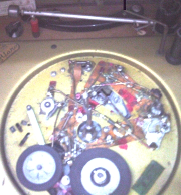
Identifying the different versions of the Collaro TSC-640 Conquest:
|
Early Collaro cam shaft
|
Early Collaro rocker arm. This
raises the pickup arm. This will
be modified for the cue control.

Fulcrum ↑ ↑ Height
adjust 2
Lift tab here
|
Wide Collaro arm head
|
Later Collaro
setdown screw
Here
←
|
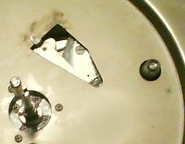
- On the early TSC-640, the change cycle cam shaft protrudes through a hole in the plinth
under the turntable. A circlip holds the cam in place. This is the round object at the right
side of the first photo (left) here:
- On these early TSC-640s, the setdown adjustment is the screwdriver slot seen in the
strange-shaped hole in the plinth.
- This setdown adjustment is accessed through a hole in the turntable by lifting the
mat.
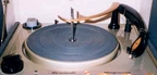
- The early TSC-640 has a rectangular rocker arm for raising the pickup arm (second photo,
above).
- An earlier version has a hole in the overarm.
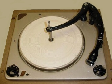
- The TSC-640/200 has the narrow pickup arm with a front-and-back mount for a ceramic
cartridge. This was used in Magnavox consoles. It appears in the photo at the top of this
page.
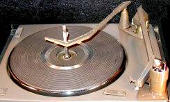
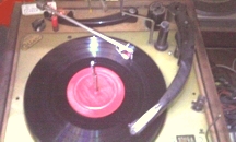
- Other versions of TSC-640 have a wide pickup arm head with a standard 1/2-inch two-hole
cartridge mount. It is seen on the Conquest in the third photo above.
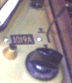
- The later TSC-640 has no hole in the plinth for the change cycle cam shaft. A circlip
holds the cam in place from the bottom. Other linkages appear where the first photo shows
the hole.
- On these later TSC-640s, the setdown adjustment is a screwdriver adjustment on top of
the plinth between the arm shaft and the restpost (bottom right of 4th photo above).
- Some of these later units have a different spindle.
Note that the turntable stop and autospeed devices require the cam shaft that protrudes
through the hole. The new cam is attached to that shaft.
Note that the cue control requires the rectangular rocker arm (second photo above).
Note that different methods must be used to make the Conquest index 6-inch records
for the narrow and wide pickup arm heads.
Identifying other kinds of Collaro and Collaro/Magnavox changers:
|
Earlier Collaro
|
Collaro Conquest
|
Collaro Conquest type
|
|
Collaro after 1966
|
Collaro after 1966
|
Pro Collaro after 1966
|
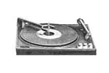
- Earlier Collaro changers do not touch the edge of the record with the pickup arm to
find the record size. Most have falling record sensors.
- These changers can't use any of these modifications.
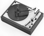
- The Collaro Conquest changers mentioned in the section above touch the edge of the
record with the pickup arm to find out the record size.
- This pyramid-arranged intermix handles odd-sizes.
- It always moves the arm back over the restpost between feeling the size and
setting the stylus on the record.
- These are based on the Collaro Conquest.
- Collaro changers made after 1966 touch the edge of the record with the pickup arm.
- These have a pyramid-arranged intermix that works with only the three
standard sizes.
- The arm stays next to the record edge after feeling the size.
These post-1966 changers can have only the following modifications from this page:
- Take-away Overarm (Pro unit was made with this)
- Fit a magnetic cartridge (different bracket) - Pro unit has this)
- Use repeating discs as described (no modification)
But many of them already have these features:
- Pro units have standard two-hole cartridge mounts and magnetic pickups
- Many have Improved arm bearings
- Some have antiskate
- Many have cue controls
- Some have pitch controls
- All of the Collaro units after 1962 have synchronous motors.
Micro-Mini
Mag Mini
Magnavox also sold several changers that were not made by Collaro:
- Magnavox used Webster-Chicago changers before they started using Collaro in
1954.
- In 1962, Magnavox used V-M changers during a Longshoremen's strike that prevented
shipping Collaro changers to the US.
- The Magnavox Micro-Mini (upper right) is a 2-speed changer indexed for size and
speed by hole size.
This was made by Philips and sold in the 1970s. It has a forked
overarm and a tracking-pad arm.
- V-M also made a small budget changer Magnavox sold in the 1970s (lower right).
It has separate speed and size selector switches.
The OFF-ON-REJ control is on the rest post and clamps the arm to the rest in
the OFF position.
- Magnavox also used many substitution changers during World War II.
- Magnavox bought Collaro in 1960 and was bought by Philips in 1974,
explaining the alternate changers in the 1970s.
None of the modifications on this page will work on any of these non-Collaro
changers except that the repeating discs work on all records on the two sold in the
1970s.
Some of these modifications must not be done if the antique nature of the record
changer must be preserved. Cutting metal or drilling holes removes any antique value
the changer might have. But note that there is yet little antique value because so many
of these Collaro Conquest changers still exist.
Cue Control
The modifications that cause these permanent changes to the Collaro Conquest
include:
- Quieter Motor and Turntable
- Increase Arm Travel for 4-inch Records
- Add Auto Record Size Range to TSC-640/200
- Improved Arm Bearings (but not antiskate)
- Cue Control (right)
- Turntable Stop
- Autospeed
- Pitch Control for early TSC-640 models
The following modifications do not cause permanent changes:
- Use trip-defeat manual start (no modification)
- Take-away Overarm
- Dual-range record size index for other TSC-640 models
- Antiskate
- Use repeating discs with all TSC-640 models (no modification)
The following are ways to improve the performance of a Collaro Conquest.
USING THE COLLARO TRIP-DEFEAT MANUAL START
There is a way to achieve full manual start on any Collaro Conquest. It is not found in
the instructions.
- Place the record on the turntable and the pickup arm on the rest post.
- Turn the changer off it is on (Automatic control to Stop or Off).
- Rotate the turntable backwards (counterclockwise) at least one rotation.
- With the changer still off, lift the arm by hand and move it as close to the spindle
as it freely goes.
- If the cue control is installed, it may be used to lift the arm.
- Move the arm away from the spindle just enough to place it in the desired place
on the record.
Trip=Defeat Manual Start
- Note: Moving the arm too far from the spindle and then moving it a
little closer again trips the changer when you turn it on.
- If you accidentally move the arm too far away from the spindle, move it
all the way close to the spindle and then try again.
- Place or cue the stylus on the record (as in photo).
- Turn on the turntable without starting a change cycle.
- Use the ON, PLAY, or MAN position, depending on the changer version
used.
- The record will play.
- If the record has a finishing groove, the changer will trip at the end
of the record.
- If the changer does not trip, turn the Automatic control to Reject.
- To stop play before the end of the record, turn the Automatic control
to Reject.
Playing the 4-inch record shown also requires the Increase Arm Travel for 4-inch
Records modification.
This process is not needed for band selection on normal records. Use it for very
small records or for short tracks near the spindle.
This process also works for all Collaro and Magnavox models with the odd-size
capability (all of the ones without red backgrounds above).
MAKE THE MOTOR AND TURNTABLE QUIETER
The motor and turntable can be made to run more quietly with these modifications:
This removes rumble and vibration.
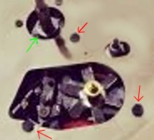
Collaro Motor and Mount
- Remove the turntable.
- Replace the turntable center bearing (green arrow) with a replacement turntable hub
ball bearing for a Garrard AT/SL record changer.
- This can be removed from a (rather useless in my opinion) B-series changer
with a size/speed knob.
- Replace both turntable center bearing washers with thin 1/2-inch washers with plated
polished surfaces. Put one on each side of the bearing.
- Remove the rubber drive wheels.
- Remove the three screws holding the motor to the plinth (red arrows).
- Buy three rubber grommets and six thin flat washers with holes that fit the screws
removed in the previous step.
- Cut the grommets in half along the groove to make 6 rubber discs with holes.
- Remove the stepped drive spindle and fan assembly from the motor shaft. They are a
press fit.
- Remove the bolts holding the bearings to the motor and remove the bearings.
- Remove the motor armature from the motor
- Chuck the motor shaft in a lathe or drill press headstock.
- Turn the chuck at low speed and slightly turn down the armature and make it smooth
with .0000 sandpaper.
- Polish the motor shaft at the bearing areas with crocus cloth.
- Clean and lube the bearing cups with #30 oil.
- Reassemble the motor shaft and bearings on the armature with the bolts. Leave the
bolts loose.
- Turn on power to the motor and tap the motor frame with a screwdriver handle. The
motor will start spinning at normal speed.
- While the motor is spinning, tighten the bolts. Make sure the motor is still turning
at normal speed. This perfectly aligns the bearings.
- Put a flat washer and then a half grommet on each screw that holds the motor in place.
The cut surface of the grommet should face away from the washer
- Put each screw in its hole in the plinth (red arrows).
- Put another half grommet on each screw with the cut surface facing the plinth. Then
add a flat washer onto each screw.
- Mount the motor on the screws.
- Tighten each screw enough to prevent unscrewing, but not enough to squeeze the
grommets down.
- Install the stepped drive spindle and fan assembly.
- Install the drive wheels.
- Adjust its height of the drive spindle height so the correct drive surfaces line
up with the idler wheel at the selected speed.
- Replace the turntable and test operation.
THE TAKE-AWAY OVERARM
Take-Away Overarm
Overarm Use
This makes the overarm removable so it does not get in the way of manual play
operation and changing large-hole records.
- Remove the circlip that holds the overarm shaft in place.
- Remove the overarm and its shaft.
- Remove the screws that hold the overarm column to the plinth.
- Remove the overarm column and rotate it 120 degrees so the notch at the top faces
the pickup arm shaft.
- The reason for doing this is to keep the overarm from pushing the last record
down with excessive force.
- This can be done because the overarm position does not cause automatic shutoff.
- If the overarm does not hold the last record well, use a grinder to slightly
shorten the overarm column at the top.*
- Reassemble the overarm column in this position and reinstall the screws.
- Leave the circlip off so the overarm can be removed when needed (You can save it for
later restoration of antique value).
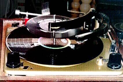
Remove the overarm when using the large-hole spindle (upper photo) or when playing
records manually for an extended time (middle photo).
Insert the overarm in its column to stack and change small-hole records
(lower photo).
Note the strobe disc in the lower photo. This is a metal strobe disc sold in the 1970s.
It must be removed to use the large-hole changer spindle.
The page author made a base for the Collaro Conquest.
- On the back side of the base, he made a socket to put the removed overarm
into to store it.
- There is also a socket for the large-hole changer spindle and one for a
single-play large-hole spindle.
- They are visible in these photos (the single-play spindle is behind the
tonearm).
The record cleaning arm is one sold in the 1970s. Do not use it with a record stack.
Note that the small-hole spindle cannot be removed.
- To place a record on the turntable, lower it to the record shelf on the
spindle and then gently push it toward the overarm shaft.
- The record will drop to the turntable.
Note that the changer was cycling when the large-hole photo was taken for another
purpose, explaining the arm position.
* Grinding the overarm column destroys antique value.
INCREASE ARM TRAVEL FOR 4-INCH HIP POCKET RECORDS
Playing a 4-inch record
Modify the trip finger
Adding extra arm travel to be able to play 4-inch Philco Hip Pocket records and other
small records
This modification is unnecessary if you have no records that play farther in than the
label edge of a 7-inch 78.
NOTE: If Increased Arm Travel, Added Record Size Range (for TSC-640/200), and
Improved Arm Bearings are all to be done, do them all at the same time.
Each one requires taking off the trip-finger/friction-clutch assembly and each one
requires a different adjustment of the assembly when it is put back.
It is better to adjust this as few times as possible because each adjustment leaves
fresh screw marks on the arm shaft. If the screw marks are too deep, the arm shaft can
be turned by removing it from the arm hinge assembly and rotating it 180°
Increasing the arm travel:
- Loosen the trip-finger/friction-clutch assembly screws.
- Remove the pickup arm and its hinge as a unit from the shaft (two screws on the
front of the hinge base).
- Remove the pickup arm shaft and the trip-finger/friction-clutch assembly from
the arm bushing assembly.
- Cut about 3/32-inch off the stop ear on the swing-in side of the assembly as shown in
the diagram (red line).
- Cut it radially to the center of the assembly's center hole.
- Make sure enough metal remains so the stop ear still stops the arm from
touching the spindle.
- It is not necessary to disassemble the clutch to do this. The part is
shown without the clutch to use an existing image.
- Do the other two modifications listed above at this time (if desired).
- If the arm bearings improvements were made, assemble the arm bearing parts on the arm
shaft.
- Partially put the arm shaft back into the arm bushing assembly from the top.
- Make sure the liftrod is in the arm shaft.
- Reassemble the trip-finger/friction-clutch assembly on the arm shaft. Do not tighten
screws.
- Fully insert the arm shaft into the arm bushings.
- Reattach the arm hinge and arm to the arm shaft.
- Adjust the trip-finger/friction-clutch assembly as detailed in the next item below.
- Check and adjust the tracking force.
- When playing a 4-inch record, the trip-defeat manual start (above) must be
used.
- When playing a 4-inch record, the strobe disc must be removed, or the record will
slip with the stylus on it.
ADJUSTING THE TRIP-FINGER/FRICTION-CLUTCH ASSEMBLY
Adjust the clutch assembly for free motion of the pickup arm as follows
- Loosen the trip-finger/friction-clutch assembly screws if they are not already
loose.
- Clip the tonearm to the restpost.
- Make sure the trip finger is in the slot of the striker feed lever (under the cam).
- Make sure the trip finger is not dragging on the baseplate.
- Stick a small flat screwdriver blade between the clutch assembly and the lower bearing
(see below).
- This makes sure it does not drag on the baseplate.
- Make sure there is a small space between the top of the clutch assembly and the arm shaft
housing and bushing assembly.
- Move the trip finger as far counterclockwise (toward the rest post) as it will go.
- Tighten the two clutch assembly screws without moving the arm of the trip finger.
- Remove the screwdriver.
- Adjust the pickup positioning lever height with the small screw behind the clutch
assembly.
- The positioning lever pin must be just clear of the cam face when the changer
is out of cycle.
- (See "GAP" in diagram at right.)
- Release and move the pickup arm to confirm the arm moves freely.
- After checking the tracking force, play some records to confirm that it correctly plays
and trips.
Do this adjustment ANY TIME the arm shaft or the clutch assembly is loosened.
ADD TO AUTO RECORD SIZE RANGE OF TSC-640/200 FOR 6-INCH RECORDS
This moves the arm rest position closer to the turntable so the arm moves farther in on the
scan to index a 6-inch record.
This modification is not necessary if you have no 6-inch records or do not want to play them
automatically.
This modification should not be made if the arm has a turnover cartridge.
- A 12-inch record will hit the stylus selector when it drops if the range is
modified.
- Alternately, the Dual Range Record Size Index (below) can be used in this
case.
- Loosen the rest post retaining screws.
- Place a 12-inch record on the turntable.
- Move the rest post closer to the turntable until the left edge of the arm on the post is
about 1/4-inch outside the record rim horizontally.
- Tighten the rest post retaining screws.
- Clip the tonearm to the restpost.
- Adjust the trip-finger/friction-clutch assembly as detailed above.
It may be necessary to remove some rubber from the rest post pad so the arm can set on a
12-inch record.
It also may be necessary to enlarge the holes for the rest post screws in the
direction the rest post needs to be moved.
Note that doing either of these removes antique value from the changer.
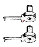
MAKE A DUAL RANGE RECORD SIZE INDEX FOR OTHER TSC-640 MODELS
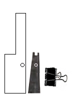
Restpost Extender
This makes a second rest post that clamps to the existing rest post to move the rest
position and index range closer to the spindle.
- This works to add ability in the 6-inch range by removing ability in the
12-inch range.
- It works the same way the Webster-Chicago 356 modification for 7-inch
records works.
- It will work for 6-inch children's records because no children's records
are 12-inch 78 RPM.
This works where the record size range modification above will not work:
- It works where the arm has a wider head.
- It works with a turnover cartridge.
- It works if the owner does not want to destroy antique value.
Make the restpost extender:
- Use any rigid material available. Suggestions include metal, wood, plastic, or
(for experimentation) even cardboard.
- The height of the step equals the height of the restpost.
- The width of upper part of the step should be just wider than the width of the arm
at the rest post. The lower part should be twice this width.
- Use a spring clip (shown) to attach the extender to the restpost.
- Drill a hole so the peg on the restpost for the arm clamp spring goes through the
hole when the extender is spring-clipped in position.
- The extender is in position when it is resting on the plinth and is
lined up with the back of the restpost.
- This might work better with two of these extenders, one on each side of the
restpost.
Install the restpost extender:
- Use the spring clip (shown) to attach the extender to the restpost.
- Place the extender in front of the rest post (on the side of the user) so it overlaps
it at the lower right corner.
- If using two extenders, put one on each side of the rest post.
- The notch belongs on the side toward the spindle.
- The peg on the restpost must be in the hole in the extender.
- The extender must be perfectly vertical. Make sure it can't move when the arm swings
out against it.
- Place the pickup arm on the notch of the extender.
Using the small size range:
- Place the pickup arm on the notch of the extender.
- Place records ranging from 10-inch to 6-inch in pyramid order on the spindle.
- The records will play and the changer will shut off, leaving the arm on the
extender.
Returning to the normal size range:
- Unclip and remove the extender from the restpost.
- Place the pickup arm on the restpost.
- Start the changer without any records. This will reset it to normal size range.
- Play records normally.
IMPROVED ARM BEARINGS AND ANTISKATE FOR ALL COLLARO MODELS
Better bearings and an antiskate compensator can be added to any Collaro TSC-640:
IMPROVED ARM BEARINGS
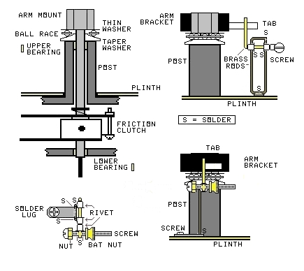
New Collaro Arm Bearings
You need the following:
- A replacement turntable hub ball bearing for a Garrard AT/SL record changer.
- This can be removed from a (rather useless in my opinion) B-series changer
with a size/speed knob.
- The page author bought a box of 20 replacement bearings from a supplier
selling off stock.
- A thin flat washer with a hole the size of the arm shaft and a diameter large enough
to cover the bearing.
- A 3/32-inch thick flat washer with a hole the size of the arm shaft and a diameter
large enough to cover the bearing.
- A way to machine the thick washer to a cone shape on one side and to slightly turn
down the arm shaft.
- The page author had a metal lathe available.
- An angle grinder and thick flat wheel to reduce the height of the arm bushing
assembly.
Procedure:
- Loosen the trip-finger/friction-clutch assembly screws.
- Remove the pickup arm and its hinge as a unit from the shaft (two screws on the
front of the hinge base).
- Remove the pickup arm shaft and the trip-finger/friction-clutch assembly from
the arm bushing assembly.
- Do the other two modifications (above) first if they are being done together.
- Remove the pickup arm shaft from the arm hinge assembly with the two screws in front
of the hinge.
- Turn down the arm shaft slightly along its entire length. Crocus cloth or #0000 aluminum
oxide sandpaper is probably enough to do the job.
- The shaft must be turning when this is used (I had a lathe, but an electric
drill will work).
- Machine the thick flat washer to a taper similar to that in the diagram.
- Make sure the balls in the bearing race, not the race itself, contact the
taper.
- Assemble the thin washer, the ball bearing, and the tapered washer (tapered side up)
onto the pickup arm shaft as in the left diagram.
- Measure the total thickness of the washers and bearing when assembled.
- Use the angle grinder to shorten the arm bushing assembly (POST in the diagram) just
enough to make room for the bearing.
- Make sure the top of the bushing assembly is perfectly flat and
horizontal.
- Make sure the liftrod is in the arm shaft.
- Put the arm shaft back into the arm bushing assembly.
- Put the pickup arm hinge back on the arm shaft with the arm on the rest post.
- Reassemble the trip-finger/friction-clutch assembly on the arm shaft. Do not tighten
screws.
- Thoroughly mix 50% #10 oil and 50% Vaseline and apply it to the ball bearing.
- Adjust the trip-finger/friction-clutch assembly as detailed above.
Test the arm and changer to make sure everything works.
ANTISKATE
Antiskate for Collaro
You need the following:
- A 1.5-inch 8-32 thread brass bolt
- An 8-32 thread brass hex nut
- An 8-32 thread brass battery terminal nut
- Some 1/32-inch brass rod stock
- Some brass rivets that slip easily over the rod stock, but with very little play
- Long solder lugs that fit the existing screw on the plinth to the right of the arm.
- A soldering iron and electronics solder.
Procedure:
- Unhook the tracking force adjustment spring from the tab on the right side of the arm
hinge.
- Reconnect the tracking force adjustment spring to go around from the back edge of
the tab instead of through the hole of the tab.
- This moves the end of the spring away from the new antiskate lever.
Make the armature:
- Screw the hex nut all the way onto the bolt and solder it to the bolt head.
- Cut a 2-inch long piece of the brass rod.
- With pliers, wrap one end of the cut rod tightly around the screw near the end with
the head.
- The end of the rod should curve like a question mark ("?") so the rod is
perpendicular to the screw.
- Put a rivet on the rod with the wide end toward the screw.
- Screw the battery nut onto the screw so it almost touches the flange of the rivet.
- Lay the rod on the edge of a flat table and see which end of the screw is heavier.
- Adjust the position of the bent rod end on the screw so the head end is slightly heavier
with the battery nut against the rivet on the rod end.
- Back the battery nut off and solder the rod end and the rivet to the screw.
Make the stand:
- Make the stand that holds up the antiskate armature (see diagram). It's construction is
not critical, except that it must do the following:
- It must hold the two rivets that are bearings for the armature shaft.
- It must be rigid enough that it can't move.
- It must hold the armature shaft perfectly horizontal.
- It must hold the armature shaft 1/4-inch below the bottom of the tab on the arm
hinge assembly.
- The armature shaft must go straight to the right from the arm shaft.
- It must not interfere with the motion of the armature or the arm tab.
- The solder lug will hold it in place using the screw found to the right of the arm
shaft.
- Do not fasten the stand to the changer yet.
- Insert the armature into the stand.
- Bend the armature shaft at a right angle to the shaft close to the stand rivet.
- It must also be at a right angle to the screw and pointing up when the head
of the screw is to the left, as in the diagram.
- Hold the shaft and rivet with pliers so they do not bend when the armature
shaft bends.
- Cut off the end of the armature shaft 1/2-inch from the bend.
- Make sure the armature turns freely in its bearings.
- Mount the stand as shown. The end of the armature must be to the left of the tab as
seen from the screw.
- Make sure the armature is free to move and follows the tab when the arm moves.
- Adjust the tracking force for the correct value.
- Adjust the antiskate with the battery nut so the pickup stylus does not move in either
direction when the arm sets down.
Test the arm and changer to make sure everything works.
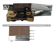
ADD A CUE CONTROL TO EARLY COLLARO TSC-640 MODELS
Cue Control Handle
Cue Control Linkage
Each part is described from the color-coded photo, with accessory drawings as needed:
Adjust the position of the cue lever by bending the cue link at the zigzag (keeping the
long parts of the link collinear) to position the cue lever for an easy-to use range.
Test the Cue Control to make sure it works.
The cue control should not affect the change cycle.
FIT A MAGNETIC CARTRIDGE TO COLLARO TSC-640/200
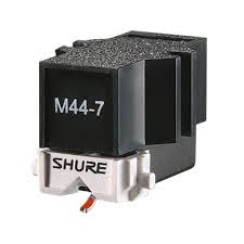
Shure M44 cartridge
Cartridge brackets
Original top
M44 bottom
I used a Shure M44 cartridge for my original modification. Amazingly this cartridge is
still in production over 40 years later.
My original modification used the M44-E, but the version sold today is the similar
M44-7. Both are quite viable for this use.
In addition, I bought many N44-E styli, plus several N44-3 styli for 78 RPM records.
You change stylus size by switching styli.
The other Collaro models have a wide head allowing the standard 2-hole mount.
I did not photograph the mount I used because the parts for it are no longer made.
Make a flat metal strap the size of the strap holding the ceramic cartridge. See
image.
Drill and tap two holes in the strap to fit the original screws for the cartridge:
Measure the original position of the stylus in the arm.
If the changer is to be used for 4-inch records, move the stylus position measured point
toward the arm hinge by 1/8-inch.
Remove the 1/2-inch mounting ears from the sides of the new cartridge.
- Make sure the cartridge is k=lined up perfectly with the old one.
- Fasten it to the mounting strap with the stylus at the measured point. Use
glue or some other kind of fastening.
Connect the correct terminals for the pins on the new cartridge to the tonearm
wiring.
Install the cartridge and measure the tracking force. The new cartridge weighs much
more than the old one.
Calculate how much weight must be added to the counterweight to remove the excess
tracking force.
Make and install an extra counterweight to take off the extra tracking force.
- The page author made a mold from the upper part of the existing
counterweight.
- Then he poured the calculated amount of molten solder into the mold.
- Then, using a longer screw, he put the new weight between the arm hinge
bracket and the existing counterweight.
Measure how much lower the stylus is in the arm than the old one. It may be necessary
to reduce the maximum number of records in a stack.
Check and adjust the tracking force.
Test the arm to make sure it plays records properly.
USE REPEATING DISCS WITH ALL COLLARO TSC-640 MODELS
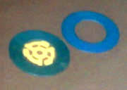
Repeating discs
There is a way to make the changer repeat a record in the stack with a 2.75-inch
repeating disc.
- Place the record to be repeated in the stack normally.
- Put a repeating disc on top of the record to be repeated.
- Place another record the same size as the record to be repeated next in the stack.
- When the changer plays the stack, the record to be repeated will play twice.
These 45 Repeating Discs were sold by Audiotex in the 1960s and 1970s. Use a spider for
the small hole spindle.
For small hole records, you can make a repeating disc by making a .075-inch thick plastic
disc 2.75-inch in diameter with a 5/16-inch center hole.
But a large hole disc must be thicker at the outer edge than it is at the inner edge so it
works with slicer spindles.
The second record is needed because the arm feels the second record instead of the original
record just before the repeating disc drops.
This trick works for all Collaro Conquests, Collaro TSC-740s, and all Collaro and Collaro
Magnavox changers with pyramid-arranged intermix made after 1954.
ADD TURNTABLE STOP TO EARLY COLLARO TSC-640 MODELS
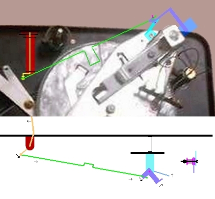
Parts location
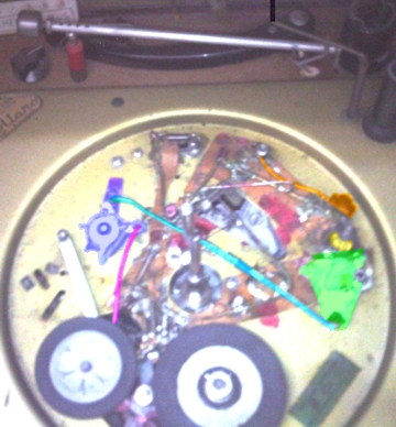
Turntable Stop Mechanism
The Turntable Stop makes the turntable stop rotating just before the record drops.
- It starts rotating again just before the arm sets down.
Turntable Stop does not completely stop the turntable at 78 RPM.
- Stopping the turntable totally at 78 makes the records already on the
turntable slip on each other.
- So it slows the turntable instead of stopping it at 78.
Note that the page author did not have machine tools available when he made the
Turntable Stop and Autospeed devices.
- He made them out of materials he already had and used tools and methods
he had available.
- Thus the original design was made out of copper and brass parts and
soldered together.
- It does not photograph well (right).
The entire mechanism, except the cam lobe and feeler arm, is built on a copper
baseplate that can be removed.
- The red markings are match marks so the baseplate can be reinstalled
correctly.
Construction methods are not critical.
The important idea is that the parts are strong enough and move correctly, not how
they look.
Build this out of what you have.
Each part is described from the color-coded photo, with accessory drawings as needed:
- Yellow - New cam lobe - The shape and orientation are clearly visible. It rotates
clockwise during the change cycle.
- Green - Idler holdout bell crank - The pivot is the black object to the right.
- The crank rotates clockwise when the cam rotates away from the out-of-cycle
position as its cam follower follows it.
- It rotates anticlockwise at the end of the cycle as the cam pushes it
back.
- Cyan (teal) - Turntable Stop Master Link
- This link moves to the left when the change cycle starts, activating parts
that pull the idler wheel away.
- A compression spring just to the right of the changer spindle pushes
the link to the left.
- At the end of the change cycle, the idler holdout crank pulls the link to
the right.
- Light Blue - Idler control crank set rotates anticlockwise when the master link
moves to the left.
- First the spring and then a tab pull the idler wheel away.
- At the end of the cycle, the parts reverse direction, letting the idler
drive the turntable.
- Magenta - Idler pull away link
- The idler control crank pulls this link toward the top of the photo.
- The hidden end of the link curves around the idle jockey arm, pulling
the idler away from the motor and turntable.
- At the end of the cycle, the tab releases the idler first.
- The spring on the control crank holds the idler back from full engagement
so the turntable doesn't suddenly jerk.
- Then the spring releases the idler a second later so it can drive.
- Orange - Turntable brake
- This pushes a rubber brake against the turntable rim when moved by the
new cam lobe just before the record drops.
- It is then immediately released so the turntable can rotate again.
Because of setbacks the author has had, the following details will be added later:
- Make the new cam lobe:
- Make the baseplate:
- Make the idler hold-off assembly:
- Make the turntable brake:
ADD AUTOSPEED TO EARLY COLLARO TSC-640 MODELS
|
Out of cycle

|
Large record
|
Small record

|
Autospeed in use

Autospeed Mechanism
The Turntable Stop must be added before adding Autospeed.
- Autospeed uses some of the parts and motions in Turntable Stop.
Autospeed detects the difference between large (>9-inch) and small (<9-inch)
records.
Autospeed allows a mixed-speed stack of large 33 RPM records followed by small
45 RPM records.
The 45 RPM records must have adaptor spiders in the large holes to make them fit
the small spindle.
The photo at the top of this page shows my Collaro playing a mixed speed stack.
This changer can play large 45 RPM or small 33 RPM records, but not in a
mixed-speed stack.
Autospeed uses the feeler arm shown in the three photos above.
- Large records (>9-inch) stop the feeler arm from moving fully in
(middle photo).
- Small records (<9-inch) let the feeler arm move fully in
(right photo).
During the change cycle, the feeler arm moves in and then retracts (left photo)
before the record drops. It feels the unplayed stack.
A latch is set when the changer is started for Autospeed:
- The user turns the speed knob to 33
- then turns the Automatic control to START and holds it there
- while turning the speed knob to 45
- and then finally releases the Automatic control.
The latch holds the speed assembly in the 33 position
- and the changer will play all of the large records (which must be first
anyway) at 33 RPM.
When there are no large records left on the spindle, the feeler arm moves fully in
and releases the latch.
- This lets the speed assembly move to 45 RPM. The remaining records will
play at 45.
If the changer is started without turning the speed control while holding the
Automatic control in START, it will operate as though Autospeed is not installed.
If Autospeed is accidentally engaged, remove the records from the spindle and
turn the Automatic control to START.
- The changer will clear Autospeed and shut off.
Each part is described from the color-coded photo, with accessory drawings as needed:
- Red - Autospeed engage crank
- This rotates clockwise to engage the autospeed latch (purple) through the
engaging spring (magenta).
- This happens when the Automatic control is turned to Reject.
- This part is curved to keep it from interfering with other parts.
- The pivot is just to the right of the record spindle. A piece of piano wire
stiffens it.
- Purple - Autospeed latch
- This piece is rotated clockwise to engage it.
- If the speed control is in 16 or 33, it moves under the idler jockey arm and
latches in place.
- If the speed control is turned to 45 or 78 while Reject is held, the
latch keeps the jockey arm at 33.
- It will remain there until there are no large records left on the spindle.
- If the speed control is already set to 45 or 78, the latch moves against
the jockey arm and does not latch.
- Magenta - Autospeed latch engaging spring
- This is pulled against the latch post by the weak spring (blue) to keep it
from rattling.
- When the Automatic control is in Reject, it pulls the latch clockwise to
try to latch it.
- Blue-Violet - Latch rail
- This holds the latch so it won't move up or down with the jockey arm.
- It is always positioned so the latch will hold the idler at 33 when
latched.
- Cyan (teal) - Latch release spring
- Pulls the latch away from the jockey arm when it is released.
- Most of it is under the change cycle drive wheel and is anchored to the
baseplate under it.
- Blue - Autospeed engage crank tensioning spring
- Pulls crank toward the Reject position weakly to keep it from rattling.
- Orange - Autospeed test slide
- The new cam lobe moves the test slide to the left shortly after the change
cycle begins.
- This causes the Autospeed arm to check for large records.
- Just before the turntable brake is applied, the slide is released by the cam
lobe.
- A compression spring moves it back to the right.
- Yellow - Autospeed crank
- The Autospeed test slide rotates the crank anticlockwise.
- The crank then pulls the Autospeed test spring to the left.
- The parts move back to their initial positions before the record drops.
Springs pull them back.
- Yellow-Green - Autospeed test spring
- This is pulled by the crank to move the Autospeed feeler link and arm to
the left.
- Green - Autospeed feeler link and arm
- This is pulled to the left by the test spring.
- It pulls the green link (under the plinth), which pulls the short green lever
to rotate the feeler arm anticlockwise.
- The feeler arm rotates until it contacts a record or comes to the end of its
travel (photos above).
- When the Autospeed parts return to rest, a spring under the plinth pulls
the feeler arm back to its rest position (left photo above).
- Aqua - Autospeed test lever and latch
- A wire spring weakly pulls the lever clockwise when not held by the latch.
- The latch is engaged by the Reject position as shown above.
- When the autospeed feeler link moves to the left, it contacts the test lever.
- If there are no large records on the spindle (third photo above), the test
lever rotates anticlockwise and releases the latch.
- If the speed control is in the 45 or 78 position when the latch is released,
the speed jockey falls to the position selected by the speed control.
- This changes the turntable speed to the small-record speed (usually set to
45).
Because of setbacks the author has had, the following details will be added later:
- Make the feeler arm assembly and link:
- Make the feeler arm test slide and crank:
- Make the latch assembly:
- Make the test lever and latch:
- Make the engage crank:
ADD A PITCH CONTROL TO EARLY COLLARO TSC-640 MODELS

Pitch Knob
This trick works for Collaro Conquests with induction motors. The speed pulley
is slightly large, so the Collaro runs slightly fast.
- The pitch control brings the speed to the correct value or slightly lower.
Note: some later Collaros have synchronous motors. This pitch control does not work with
those.
The induction motors are rectangular. The synchronous motors are cylindrical.
The pitch control is the black knob seen on the base in the left back corner. It is
clearly visible in the first photo on this page and also to the right.
This pitch control causes a variable slippage in the rotating magnetic field of the
induction motor, slowing it down by a controlled amount.
- The rheostat that knob controls adjusts the amount of slippage by putting
some direct current on the motor winding.
Pitch Circuit
Making the Pitch Control:
- Make sure that all connections are insulated so no person can accidentally touch them
while working on the Collaro.
- If you have a base for the Collaro, find a place on the base to put the pitch
control.
- Make an enclosure for the rheostat and the diode to prevent accidental contact
with live parts.
- Make sure that the rheostat, the diode, and the enclosure do not
interfere with the operation of the changer.
- When choosing the 4-pin plug and socket, make sure they have insulating covers.
- If the plug and socket covers have holes for wires, be sure to feed the wires
through the holes before soldering them to the connectors.
Wire the 4-pin socket into the Collaro wiring:
- Cut the wire leading from the changer power switch to the motor (usually yellow).
- Be sure to cut it on the motor side of where the amplifier power lead
connects to this wire.
- Leave enough wire for an insulated splice on each side of the cut.
- Splice a wire to the motor side of the cut wire and insulate the splice. Connect the
other end of the new wire to pin 4 of the 4-pin socket.
- Splice a wire to the switch side of the cut wire and insulate the splice. Connect
the other end of the new wire to pin 3 of the 4-pin socket.
- Connect the amplifier power lead to the live side of a cord-mount power socket.
- Tap two wires off of the wire from the motor to the power neutral connection and
insulate the tap.
- Connect one of these wires to the neutral side of the cord mount power
socket.
- Connect the other wire to pin 2 of the 4-pin socket.
- Tap one wire off of the wire from the switch to the power live connection and insulate
the tap. Connect it to pin 1 of the 4-pin socket.
- If one has not been provided, replace the connection for power live and power neutral
with a power cord with a properly connected polarized plug.
- Insulate all splices made for this.
Wire the dummy connector:
- Connect a short piece of wire from pin 3 to pin 4 of a 4-pin plug.
- Put the cover on the plug.
- Keep this plug to substitute for the speed control plug when servicing the changer
away from the base.
Pitch Circuit
Wire the speed control and lights:
- Make all of the connections inside the plug cover or inside the rheostat cover.
- Any holes the wires run through must have grommets.
- The lights shown are neon, but they can be LED pilot lights.
- The author used neons because LED pilot lights were not yet available when
he built this.
- Mount the rheostat and the enclosure on the base.
- Leave the cover off the enclosure so the wires can be soldered.
- Mount the lights on the base.
- Make sure their leads are long enough to reach the plug and inside the
rheostat enclosure.
- Solder one end of the diode to the clockwise pole of the rheostat.
- The diode polarity is not important for this purpose (the schematic shows
the cathode connected here).
- Also solder a lead from terminal 4 of the plug to this terminal.
- Solder the other end of the diode to both the rheostat armature pole and the
counterclockwise pole (if one exists).
- Also solder a lead from terminal 3 of the plug and one lead from each
lamp to this terminal.
- Solder the other wire from the red light to terminal 1 of the plug.
- Solder the other wire from the orange light to terminal 2 of the plug.
- Put the covers on the plug and the rheostat enclosure.
Assemble the Pitch Control:
- Plug the plug into the socket on the changer.
- Mount the changer in the base if it was removed to mount the speed control.
Testing and operation:
- Plug the changer into a power socket.
- When the changer is off, the red light should be on.
- When the changer is on, the orange light should be on.
- Using a strobe disc and suitable light, measure the speed of the turntable.
Adjust it with the pitch control.
- Note that the changer might not be able to complete a change cycle if the pitch
control is set too low.
- If this happens, turn the pitch control to maximum to start the motor again.
APPENDIX 1:
TESTING OTHER RECORD CHANGERS FOR THESE FEATURES:
| |
|
|
|
|
|
|
|
|
|
|
|
|
|
|
| CHANGER |
N
O
S
T T
R A
I R
P T |
4
−
P I
L N
A C
Y H |
O
D
C D
H
A S
N I
G Z
E E |
M S
I I
X Z
E E
D S |
P
L
A
T S
T T
E O
R P |
M S
I P
X E
E E
D D |
I
N
R
E S
P T
E A
A C
T K |
A B
R E
M A
R
B I
A N
L G
L S |
S
A K
N A
T T
I E |
L
C I
U F
E T |
P
F I
I T
N C
E H |
T
A O
K V
E E
A R
W A
A R
Y M |
F
E
A C
T O
U U
R N
E T |
NOTES |
| My Collaro Conquest |
YES | YES | YES | ARR | YES | ARR |
DISC | YES | YES | YES | YES | YES |
12 | Specially modified |
| Collaro Conquest (stock) |
YES | no | LESS | ARR | no | no |
DISC | no | no | no | no | no |
4 | |
| Collaro PH-1252 |
no | no | no | ARR | no | no |
DISC | YES | YES | YES | no | YES |
6 | |
| Dual 1004 |
no | no | YES | RND | YES | no |
YES | YES | no | no | no | no |
5 | |
| Dual 1006A |
no | no | LESS | RND | no | no |
YES | YES | no | no | no | NONE |
5 | |
| Dual 1219 |
no | no | no | no | no | no |
no | YES | YES | YES | YES | NONE |
5 | |
| Garrard SL-65 |
no | no | no | RND | no | no |
ACC | YES | YES | YES | no | no |
5 | Single play repeat needs a spring clip |
| Glaser-Steers GS-77 |
YES | no | no | RND | YES | RND |
no | no | no | no | no | no |
4 | |
| Luxor RT-21 |
YES | no | YES | RND | no | no |
DISC | no | no | no | no | no |
4 | |
| PE 2038B |
no | no | no | no | no | no |
YES | YES | YES | YES | YES | NONE |
6 | Modified for repeating disc and position |
| PE REX AA |
no | no | YES | RND | no | no |
no | no | no | no | no | NONE |
3 | |
| Philips AG-1024 |
no | no | no | RND | no | no |
YES | no | no | no | no | YES |
3 | Repeat Single or set size with disc |
| Webcor 1854 Magic Mind |
no | no | no | RND | no | RND |
no | no | no | no | no | no |
2 | Auto speed change cannot be turned off |
| UQ Autosides (hypothetical ideal) |
YES | YES | YES | ARR | YES | ARR |
YES | YES | YES | YES | YES | NONE |
12 | |
Key to table above:
- ACC - Accessory needed for single play repeat
- ARR - Arranged intermix (larger must be below smaller)
- DISC - Can use repeating discs
- LESS - Odd size capability does not include 6-inch records
- NONE - Changer has no overarm (counted as having the feature)
- RND - Random intermix order
APPENDIX 2:
CASES WHERE ALL RECORDS BY ONE ARTIST OWNED BY AUTHOR CAN'T BE PLAYED IN
ONE STACK:
| ARTIST | REASON ALL RECORDS CAN'T BE IN ONE STACK |
|---|
| ABBA | Too many records |
| Herb Alpert and the Tijuana Brass | Too many records |
| The Association | Has 4-inch 45 RPM record |
| Beach Boys | Has 12-inch records at both 33 and 45 |
| Rosemary Clooney | Has 78 RPM records too |
| Perry Como | Has 78 RPM records too |
| Deep Purple | Has 7-inch records at both 33 and 45 |
| Neil Diamond | Too many records |
| Tommy Dorsey and Orch | Has 78 RPM records too |
| Doobie Brothers | Has 7-inch records at both 33 and 45 |
| The Doors | Has 4-inch 45 RPM record |
| Duke Ellington and Orch | Has 78 RPM records too |
| Percy Faith and Orch | Has 78 RPM records too |
| Tennessee Ernie Ford | Has 78 RPM records too |
| Kool and the Gang | Has 12-inch records at both 33 and 45 |
| Barry Manilow | Has 12-inch records at both 33 and 45 |
| Meco | Too many records; Has 12-inch records at both 33 and 45 |
| The Monkees | Too many records |
| Glenn Miller and Orch | Has 78 RPM records too |
| Ohio Express | Too many records |
| Shadows of Knight | Has soundsheet |
| Steppenwolf | Too many records |
| Donna Summer | Has 12-inch records at both 33 and 45 |
| The Three Suns | Has 78 RPM records too |
| John Williams and BPO | Has 7-inch records at both 33 and 45 |
| |
The main reasons the page author has artists with records that cannot all be stacked
together on this Collaro are:
- Too many records to fit in one stack
- Some albums are CDs (not listed above)
- Has 78 RPM records
- Has 12-inch 45 RPM disco singles and 12-inch 33 RPM albums
- Has 12-inch 45 RPM classical albums and 12-inch 33 RPM albums
- Has 7-inch 33 RPM jukebox albums and 7-inch 45 RPM singles
- Has original Columbia 7-inch 33 RPM singles and 7-inch 45 RPM singles
- Has 7-inch 33 RPM album supplements and 7-inch 45 RPM singles
- Has soundsheets or Hip Pocket records that can't be dropped
- Has a record set recorded in manual sequence (can't play correctly in stack)