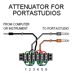
- Mount the terminal strip centered on the wood with the screws. Now turn the wood so the ends of the terminal strip point left and right for the remaining steps.
- Mark the terminals 1 to 6 in order from left to right. The two rows of terminals will be designated the upper row and the lower row.
- Cut the 1/4" plug patchcord in half in the middle.
- Remove the sheath back 1.5 inches on both cut ends. Separate the shields from the center conductors, and strip the center conductors 3/8" back from the ends. Twist the strands of the shields together.
- Cut the 1/8" plug patchcord about 6" from one end (the OTHER end MUST have the 1/8" TRS plug). NOTE: If you
are making two, cut the 1/8" patchcord into two equal lengths.

- Cut a 2" piece of cable from the short end. Discard the rest of short end (or save it for another use).
Note: If you bought the 12' patchcord to make two units, only one 2" section must be cut, from the middle where you cut it in half. You get 2 short wires out of the one 2" piece, one for each attenuator.
- Pull the wires out of the 2" cut piece. Strip the ends of one of the insulated wires back 3/8"
- Remove about 3" of sheath from the cut end of the long piece of 1/8" plug patchcord. Strip the center conductors back 3/8". Twist the strands of the shield together.
- In the following 6 steps, shorten the leads of the resistors if necessary, so there are no long lengths of bare lead exposed.
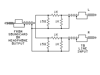
- Connect one 15-ohm resistor between lower terminals 2 and 3. Tighten terminal 3, but leave 2 loose.
- Connect the other 15-ohm resistor between lower terminals 4 and 5. Tighten terminal 4, but leave 5 loose.
- Connect one 1K resistor between lower terminals 1 and 2. Tighten the terminals. Place the resistor so its leads cannot touch the lead to terminal 3.
- Connect the other 1K resistor between lower terminals 5 and 6. Tighten the terminals. Place the resistor so its leads cannot touch the lead to terminal 4.
- IF your output is expected to exceed 2 volts, connect one 1K resistor between lower terminals 1 and 3, after loosening those screws. Then tighten the screws. Place the resistor so its leads cannot touch the lead to terminal 2.
- IF your output exceeds 2 volts, also connect one 1K resistor between lower terminals 4 and 6, after loosening those screws. Then retighten the screws. Place the resistor so its leads cannot touch the lead to terminal 5.
- Cut off any excess length of the shields of all of the cables, until the shield sticks out only 5/8" from the sheath. Do not trim back the insulated center conductors.
- Twist together the shield of the 1/8" cable, the shield of ONE of the 1/4" cables, and one end of the 2" wire. Connect them to upper terminal 3.
- Twist together the shield of the remaining 1/4" cable and the other end of the 2" wire. Connect them to upper terminal 4.
- Look at the colors of the insulated center conductors of the 1/8" plug cable. Connect the one that is NOT red to upper terminal 2. (If neither one is red, see the footnote below.)
- Connect the red center conductor of the 1/8" plug cable to upper terminal 5.
- Find the 1/4" plug cable with its shield already connected to upper terminal 3. Connect the insulated center
conductor of this cable to upper terminal 1.

- Mark the plug on this cable "L".
- Connect the insulated center conductor of the remaining 1/4" plug cable to upper terminal 6.
- Mark the plug on this cable "R".
Bind the two 1/4" plug cables together at 6" intervals (except the last foot of the plug ends) with cable ties to reduce hum.
- Plug the 1/8" plug into the soundcard, and the two 1/4" plugs into your mic/line inputs.