SIGNAL BASICS
The traffic signal is the cheapest and easiest way to alternate the right-of-way among various traffic streams. Otherwise, a policeman would have to be paid to do this job.
Different signal faces are green at different times, while the other faces are red. In the simplest form, the signal lets one street go, and then stops that street so the other street can go.
That depends on drivers and conditions. Traffic signals reduce the more dangerous right angle collisions, but they can increase the less severe rear-end accidents. Whether a signal reduces total accidents depends on whether or not the reduction in right angle accidents is less than the increase in rear-end accidents. But traffic signals normally reduce the severity of accidents.
No. Red-light cameras increase rear-end accidents, especially if the jurisdiction shortens the yellow change interval to increase revenue. This form of decreasing safety to increase revenue should be illegal.
The Manual on Uniform Traffic Control Devices (MUTCD) is a manual prepared by the Federal Highway Administration (FHWA) of the US Department of Transportation (USDOT). It sets requirements on the devices used on all roads and highways in the nation, including some private roads. It sets the rules for the use of traffic signals.
First, an engineering study must be done. They must collect data to see what is actually happening at the location. Different alternatives must be examined. Then the location must be checked against the warrants in the MUTCD for installing a signal. At least one warrant must be met, or no signal may be installed. Finally, funding must be secured.
There are 9 warrants:
- 8-hour traffic volume warrant with interruption of continuous traffic variant
- 4-hour traffic volume warrant
- Peak hour traffic volume warrant (e.g. factory exit)
- Pedestrian and traffic volume
- School crossing warrant
- Coordination warrant (provides for adding a signal missing from progressed signalization)
- Crash experience
- Roadway network (attracting traffic to one road, instead of neighboring residential streets)
- Grade crossing (interrupting traffic to empty grade crossing before train comes)
Only one warrant is needed to install a traffic signal.
Meeting a warrant does not require installing a signal.
If a signal no longer meets any warrants, it must be removed.
No federal funding may be used on the project.
A government that repeatedly disobeys the MUTCD can lose all federal funding for roads.
The government that installed the signal can be liable for any accidents the signal causes.
A signal can cost from a quarter million to half a million dollars to install. Over half of that cost is labor.
A signal controller and cabinet costs about $15000. A mast arm costs almost that much. Signal heads are about $1000 per signal face.
Maintenance is about $8000 per year per signal. This includes parts and labor. Relamping is the primary expense.
No, because it doesn't work. Speeds away from the sign or signal are unaffected. The ideas laymen have about traffic control are often false. This is why layman politicians should not be in charge of traffic control.
Left to himself, a driver will drive the highest perceived safe speed of the road, no matter what speed limits politicians post. Politicians often think they can make a road "safer" by designing the road for 10 mph over the intended speed limit. But then drivers want to drive 10 mph over that limit.
Nothing will ever control the speed of drivers except modifying the perceived safe speed of the road. Often drivers will speed on residential roads that are made too wide because regulations require that all fire equipment must be able to use the road.
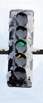
 A signal face is one cluster of signal sections facing one traffic movement. A signal face usually has
one set of red, yellow, and green lamps. A signal face appears in the image at right.
A signal face is one cluster of signal sections facing one traffic movement. A signal face usually has
one set of red, yellow, and green lamps. A signal face appears in the image at right.
Normally a signal face must have at least 3 signal sections, but it can't have more than 5 sections. An exception is a single section for a green arrow for a continuous movement or a single-section flashing beacon.
A signal section is the portion of a signal face containing one lamp assembly and visor. The signal face shown at right contains one circular red section, one circular yellow section, and one circular green section.
A signal head is a single signal face mounted alone or a cluster of signal faces aimed at different intersection approaches. Each signal head has a common mounting point.
A post mount for a signal is a signal head mounted on a vertical post. The post can be on a corner of the intersection or in a median.
A mast arm mount for a signal is a signal head mounted on a horizontal arm attached to a vertical post. The post can be on a corner of the intersection or in a median, but the arm holds the signal head over traffic lanes.
A span wire mount for a signal is a signal head mounted on a wire stretched between two posts. The posts can be on corners or in medians, but the wire holds the signal head over traffic lanes. Often a second wire across the bottoms of the signal heads keeps the wind from blowing the signal heads around.
A signal bridge mount for a signal is a signal head mounted on a horizontal arm attached to two vertical posts, one at each end of the arm. The posts can be on corners or medians, but the arm holds the signal head over traffic lanes.
 A flashing beacon is a single signal section signal face that flashes a circular red, circular
yellow, red arrow, or yellow arrow. These are used at intersections with stop-sign control as
extra emphasis warnings, or on signs as warnings.
A flashing beacon is a single signal section signal face that flashes a circular red, circular
yellow, red arrow, or yellow arrow. These are used at intersections with stop-sign control as
extra emphasis warnings, or on signs as warnings.
The rules in the MUTCD changed to make the flashing beacon look exactly like a traffic signal in flash mode. Two or more lamps placed in a general line horizontally with respect to each other must flash in unison. But two lights in a vertical line must flash alternately.
These are solar powered flashers that are not connected to each other. They are violating the MUTCD. Synchronizing wires should be connected between them.
The colors come from nautical and railroad practices.
Ships have used red, green, and white lamps for centuries to assign privileged and burdened rights of passage. A green light means the ship whose pilot sees it is privileged, while a pilot seeing the red light knows his ship is burdened, and must turn right or slow down. If both red and green are visible, the ships are approaching each other head-on, and must turn away, usually to the right. The white light indicates the ship is overtaking another ship going the same direction. Multiple white lights indicate the ship is wind powered, and is always privileged over powered craft. Multiple red lights indicate that the ship is so big that it can't change course or speed quickly.
When railroads started using colored signals, the original colors were red for stop, green for caution, and white for go. These colors were fine for signal flags. But white caused a problem at night, when engine drivers saw other lights and mistook them for the signal lights. So the colors were changed to red for stop, yellow for caution, and green for go. But railroad caution signals mean the next signal is red, because the stopping distance of a train is longer than sight distance. The automobile caution signal gives drivers time to stop for the same signal.
Aircraft use the same color codes used for ships.
These colors were chosen to prevent confusion with vehicle signals.
White was chosen first, as a fourth lens with the word WALK in it, in the 1920s.
Orange was chosen in the 1940s when pedestrian signals were separated from vehicle signals.
Originally pedestrian signals were round. They were then changed to be square for easier identification.
They actually designed standard signal colors so color-blind drivers can tell them apart:
- The red is yellowish, so protan and deutan viewers see a yellow shade or tint.
- The yellow is reddish, so tritan viewers see a red tint.
- The green is bluish, so protan and deutan viewers see a blue tint.
- Pedestrian orange needs no adjustment.
- Pedestrian white is bluish.
All of the stop indications give some sort of red or yellow stimulus to color-blind people, while all of the go indications give green or blue stimuli. The remaining indistinction is between yellow and red. The signal sequence usually provides the missing information.
The location of the lens in the signal face provides other clues.
These ideal colors had not been fully realized until LED signals appeared, because the incandescent lamps and filters could not produce the correct green bright enough to use in a signal.
For more, see this page.
The following are the meanings of the traffic signal indications:
| Steady Circular Red (SCR) | Stop* |
| Steady Red Arrow (SRA) | Stop† |
| Flashing Circular Red (FCR) | Stop and proceed when safe |
| Flashing Red Arrow (FRA) | Stop and proceed when safe† |
| Steady Circular Yellow (SCY) | Prepare to stop - right-of-way ending |
| Steady Yellow Arrow (SYA) | Prepare to stop† |
| Flashing Circular Yellow (FCY) | Caution - turns yield to conflicts |
| Flashing Yellow Arrow (FYA) | Yield to conflicting traffic† |
| Steady Circular Green (SCG) | Go - turns yield to conflicts |
| Steady Green Arrow (SGA) | Go - protected turn† |
| Steady White Man (SW) | Start and continue to cross street |
| Flashing Orange Hand (FDW) | Continue to cross, but don't start |
| Steady Orange Hand (SDW) | Do not cross street |
* Some turns may be allowed after stop according to state law.
† Only if turning in the direction of the arrow
There are three indications for general use, two indications for night flashing, and five indications intended for traffic turning in a specific direction. There are also three pedestrian indications. This is the minimum number needed to give all of the meanings needed to safely control traffic.
Yes:
- Vehicles:
- Arrows apply to only the traffic turning in the direction the arrow is pointing.
- Steady Red means stop.
- Flashing Red means stop, then proceed when the way is clear.
- Steady Yellow is a change interval. Stop or clear the intersection.
- Flashing Yellow means caution. Turns must yield to pedestrians and oncoming traffic.
- Steady Circular Green means go. Turns must yield to pedestrians and oncoming traffic.
- Steady Green Arrow means a cleared right-of-way. Go.
- Pedestrians:
- Steady White Man means you may start crossing the street.
- Flashing Orange Hand means you may continue crossing, but you may not start crossing.
- Steady Orange Hand means you must not be in the crosswalk.
- When pedestrian signals don't exist:
- A Circular Green or Green Straight Ahead Arrow means you can cross.
Start crossing only when it first lights. - Any other indication (including a Green Turn Arrow) means you cannot cross.
- A Circular Green or Green Straight Ahead Arrow means you can cross.
The flashing orange hand means:
- A pedestrian already in the crosswalk may continue to cross.
- A pedestrian not yet in the crosswalk must wait.
Yes. Here is a partial list:
- Chicago originally used red for east-west go, purple for north-south go, and yellow for change. All directions saw the same color, and all signals along the street showed the same color at the same time.
- Many early signals had no yellow light, and just changed between red and green (standard meanings).
- Maryland and DC used a white lens with the words "TURN LEFT" along with red and green.
- Many New York City signals had only red and green lights, and lit both for the change warning. Most of these had only two bulbs for all four directions, with red on top for one street, and green on top for the other street.
- Signals in the 1920s to 1940s lit all of the yellow lights at the same time to indicate a change. Some of these still exist.
- Some of the above signals had only three bulbs for all four directions. These had green on the top for one street, red on the top for the other street, and yellow in the middle.
- Some signals used green arrows to indicate that a turn was permitted, not protected. This was often done at one-way streets instead of using ONE WAY signs.
- Many older signals lit both the red and yellow just before the green, telling drivers they could shift into low before the green. This is now strictly prohibited, because too many drivers started to go on the red-yellow indication.
- Massachusetts has used simultaneous lighting of the yellow and red lights in all four directions to indicate that pedestrians can cross in any direction.
- In the 1950s, Indiana used a steady burning yellow arrow for a permissive turn, and a steady burning green arrow for a protected turn.
- In the 1950s and 1960s, Indianapolis had some square left-turn signals with the red word WAIT and the green word TURN.
- In the 1950s and 1960s, Pennsylvania lit the yellow two seconds before turning off the green, as a warning the yellow is about to start.
- Since the 1950s, Canada has used the steady green arrow to require all traffic to turn in the direction of the arrow.
- In the 1950s and 1960s, Missouri used a flashing green arrow to indicate the direction of a reversing one-way street.
- In the 1950s and 1960s, Missouri used both a steady red arrow and a flashing red arrow to indicate that all traffic must turn in the direction of the arrow.
- In the 1960s, Illinois used flashing yellow arrows and flashing red arrows to indicate that traffic must turn in the direction of the arrow. The flashing red arrow also required a stop.
- In the 1960s, California had a two-section left turn signal with just a green arrow and a yellow arrow. When neither was lit, the driver used the circular indications over the next lane.
- In Canada and most British Commonwealth countries, a flashing green arrow means a protected turn.
- From 1975 to 2012, Michigan, Maryland, Delaware, and Virginia allowed permissive left turns on a flashing circular red while oncoming traffic had a green light.
- From the mid-1980s to 2012, Washington State allowed permissive left turns on a flashing circular yellow while oncoming traffic had a circular green.
- Flashing green has been used in some places to indicate a pedestrian crossing signal that is not about to change soon. Other areas have used flashing green to indicate that the yellow is coming in a few seconds. Flashing green is prohibited by federal standards.
 A HAWK (High-intensity Activated WalK) signal is a three-section signal for a pedestrian crossing (see
illustration). It shows the following aspects in this order:
A HAWK (High-intensity Activated WalK) signal is a three-section signal for a pedestrian crossing (see
illustration). It shows the following aspects in this order:
| Dark (go) | Pedestrian signal shows steady orange hand. |
| Flashing yellow (caution) | Pedestrian signal shows steady orange hand. |
| Steady yellow (change interval) | Pedestrian signal shows steady orange hand. |
| Both steady red (absolute stop) | Pedestrian signal shows steady white man. |
| Alternate flashing red (stop and proceed) | Pedestrian signal shows flashing orange hand. |
| Dark (go) | Pedestrian signal shows steady orange hand. |
A Firehouse version of this signal omits the steady red indication.
Neither signal can be placed at an intersection.
The flashing yellow arrow permits the indicated turn after the driver yields to conflicting traffic. Conflicting traffic includes pedestrians and oncoming traffic.
See this page for more on flashing yellow arrows.
The illustration at right is a flashing yellow arrow left-turn signal face.
 For the driver turning in the direction of the arrow, both indications mean the same thing.
The difference between the indications is the meaning given to drivers not making the indicated turn.
The circular green causes a danger called yellow trap (see below), because it controls too many movements at once. It can end a permissive left turn at an unsafe time, trapping drivers in the intersection. The flashing yellow arrow prevents yellow trap, if installed properly, by ending the permissive turn at the correct time.
The flashing yellow arrow is useful for allowing permissive turns with the lead-lag signal. This is useful for signal progression. This sequence can be seen here.
Yes. The flashing yellow arrow left turn signal face tells you the color of the oncoming circular indications whenever it permits a movement:
| LEFT TURN SIGNAL |
LEFT TURN MEANING |
SIGNALS FOR ONCOMING TRAFFIC | ONCOMING TRAFFIC CAN NEVER HAVE THESE SIGNALS |
|
|---|---|---|---|---|
| EXPECTED SIGNAL |
ADDITIONAL POSSIBLE ONCOMING SIGNALS |
|||
 |
Stop and stay | ANY


 |


 |
None |
 |
Stop, turn when safe | |
Double Clear:
|
*
* |
 |
Prepare to stop | or
|
|
*
* |
 |
Yield to conflict | |
Double Clear:
|
*
* |
 |
Go - protected turn | |
|
|
|
Night Flash |
Stop, turn when safe | or
 |
|
* |
|
Night Flash |
Yield to conflict | |
|
* |
* Right turn indication may be allowed if the right turn enters an exclusive lane.
To avoid yellow trap, the permissive turn must end at or after the time the oncoming circular green ends. Ending it earlier exposes the left-turning driver to yellow trap.
Yellow trap is an unexpected and hard to recognize hazard caused by allowing left turns on a circular green. It occurs when the following happen together:
- Left turns are allowed on circular greens.
- One circular green ends before the other one does.
When this happens, a driver turning left and seeing the yellow light does not know that oncoming traffic still has a green light. He turns in front of live traffic, possibly causing a crash.
See this page for more on yellow trap.
Each flashing yellow arrow prevents the yellow trap caused by the circular green and green arrow facing the other way on the street.
Even if only one direction of flow has a green arrow, the flashing yellow arrow is needed in both directions.
Like the circular green, the circular red controls too many movements at once. It can give a conflicting indication to traffic making another movement, causing drivers to stop suddenly.
The new 2009 MUTCD requires a red arrow for all new separate left-turn signals.
Between 1971 and 2009, a circular red could be substituted for a red arrow, because the red arrow was not very bright. If a circular red was used, a sign reading LEFT TURN SIGNAL was required to be placed next to the left-turn signal. Now that LEDs provide brighter red arrows, the rule allowing a circular red was removed.
The restrictions are:
- No circular signals are allowed in faces over an exclusive left-turn lane or directly in front of the lane.
- Shared turn and thru signal faces with circular greens must be over the leftmost thru lane or over the lane line between the left-turn lane and the thru lane. This face may not be over the exclusive turn lane.
- The shared signal must be used where turns and thru traffic share a lane. This face may be over the shared lane.
- Existing circular greens can remain over the left-turn lane until the signal is redesigned.
- Any yellow trap must be eliminated or warned with a sign. This may not remain in place.
They were prohibited in the 1970s because the equivalent circular indications have the same meanings and because the arrows are harder to see.
The straight-ahead green arrow has a meaning very different from the circular green, so the straight-ahead green arrow remains. It is a movement protected from all conflicts, including protection from permissive left turns from oncoming traffic. It always shares a signal face with a circular yellow and a circular red.
 Two reasons:
- The signal lights are in a standard order so people with color blindness can tell the indications apart.
- The red is on top so it can be seen from a longer distance, or over obstacles.
A doghouse signal is a five-section signal that is shaped like a dog house. See illustration.
 A mallethead signal is a four-section signal that is shaped like a mallet (see illustration). It is used
for the flashing red arrow signal face, with the flashing red arrow at the upper right.
A mallethead signal is a four-section signal that is shaped like a mallet (see illustration). It is used
for the flashing red arrow signal face, with the flashing red arrow at the upper right.
This configuration has also been used with two circular red lights to protect drivers in case one red light burns out.
The mallethead signal has also been called a T-head signal and a mickeyhead signal.
Those are signals for light rail trains, streetcars, or special transit vehicles. Meanings for the motorman are as follows:
- A horizontal bar means stop.
- A vertical bar means go.
- A diagonal bar means the next switch is set for turning in the direction the bar slants.
- A triangle means the next signal is a horizontal bar, so slow down.
Drivers in road vehicles must ignore these signals.
 A presignal is a sign warning that a traffic signal ahead is red. It is usually used when a hill, an
overpass, or a curve hides the signal. See image at right.
A presignal is a sign warning that a traffic signal ahead is red. It is usually used when a hill, an
overpass, or a curve hides the signal. See image at right.
Sometimes a presignal is used to get heavy trucks to stop in time.
The word "RED" lights to produce the message "RED SIGNAL AHEAD" when the signal will be yellow or red when the driver who sees this message reaches the signal, or when a line of stopped traffic will still be at the light after it turns green. When the light will be green without a line of stopped traffic, the word "RED" turns off, leaving the message "SIGNAL AHEAD".
If the yellow lights are included with the above sign, they flash in unison at all times in the signal cycle in this version.
 An alternate version has a sign that says "RED SIGNAL AHEAD WHEN FLASHING". Another
alternate version has a blank-out sign that says "PREPARE TO STOP". Two yellow lights
flash in unison when the signal will be yellow or red when the driver who sees it reaches the
signal, or when a line of stopped traffic will still be at the light. When the light will be green
without a line of stopped traffic, the flashing yellow lights and the blank-out sign (if used) turn
off.
An alternate version has a sign that says "RED SIGNAL AHEAD WHEN FLASHING". Another
alternate version has a blank-out sign that says "PREPARE TO STOP". Two yellow lights
flash in unison when the signal will be yellow or red when the driver who sees it reaches the
signal, or when a line of stopped traffic will still be at the light. When the light will be green
without a line of stopped traffic, the flashing yellow lights and the blank-out sign (if used) turn
off.
Japan uses a 2-section signal with a circular green and a flashing circular yellow. The flashing yellow is on at the times when the word "RED" is lighted on the US version.
Two red lights are sometimes provided to maintain safety if a lamp burns out.
It also helps color-blind people recognize the red light.
Two sizes are used:
- Older traffic signals use lenses with an 8" (20 cm) diameter. These are being phased out.
- Most signals now have 12" (30 cm) diameter lenses. These are the size of an LP record album.
- Almost all signals now have 12" (30 cm) diameter arrow lenses.
Several technologies have been used:
- Older traffic signals use special long-life incandescent light bulbs.
- Some older traffic signals used neon tubes, especially in pedestrian indications.
- Newer signals use Light Emitting Diode (LED) signal lamps.
The following are the advantages:
- The LED signal lamp uses much less electricity than incandescent lamps, for the following reasons:
- LED technology uses less current than incandescent technology to make the same amount of light.
- LEDs don't waste energy radiating light that is not visible, such as infrared.
- Colored LEDs produce only the color needed. They don't make unwanted colors that must be filtered out.
- Arrows need LED emitters only where the shape of the arrow actually is. No masks are needed.
- LEDs produce purer colors than the filters used with white incandescent lamps.
- LEDs produce the specified green color that incandescent lamps and filters could only come close to.
- LEDs usually last much longer than incandescents, cutting maintenance costs for relamping.
 There are several reasons:
- LED signal lamps cost a lot more than light bulbs. Getting a budget for them is often difficult.
- LEDs do not get hot enough to melt snow and ice from the signal lens and visor the way incandescent lamps do. See image.
- Some older lamp drivers don't work with LED lamps. They must be replaced too, increasing the cost.
- While LEDs generally last longer, some brands don't, and environment can cause a failure. LEDs are particularly susceptible to lightning.
- When an LED signal fails, it can fail in strange ways, such as rapid blinking, dimming, part of the lens darkened, part of the lens blinking, and other unusual effects.
- The programmable restricted visibility signals need a concentrated filament lamp, not a wide LED.
CFLs burn out too fast. A fluorescent lamp's life is not measured in how much time it is lit, but how many times it has been turned on. A fluorescent lamp is good for about 6500 starts. At the normal number of times a day a traffic signal lamp is lit and extinguished (averaging 1440), the CFL would not last even one week before it failed. A flashing beacon would burn out in about two hours.
Those are indications to show a police officer that the signal face is displaying a red light. This is used for enforcement of red-light violations. But these do not show if an arrow is allowing a turn.
Those are indications to emergency vehicles that they have successfully preempted the signal. This is necessary, because an emergency vehicle might not have succeeded in taking control. Also, it is possible that two emergency vehicles are approaching the intersection from different directions. Only one of them can have control at a given time.
Various events can preempt normal signal operation, bringing into effect special signal operation. The following are special events, listed in decreasing order of priority, which can preempt a signal:
- Train on a nearby railroad crossing
- Opening drawbridge
- Emergency vehicle (police, fire, ambulance)
- Firehouse exit
- Discharging a queue of vehicles backed up into another signal or a freeway ramp
- Factory or stadium discharge
- Transit vehicle (alters signal timing, not sequence)
One of three things happens when the power fails:
- The newest signals with LED lamps have a battery backup that can run the signal normally for over 12 hours
- Older signals have a battery backup that can run the signal on night flash for several hours.
- The oldest signals have no battery backup, and go dark.
If the power is off long enough, all of the signals will go dark.
When the power comes back on, the signal that was off usually starts up in night flash mode, to warn drivers that operation is resuming. After a few minutes, the signal makes an orderly transition to normal operation.
Stop!
There are four possibilities:
- The power is completely out to the signal. Nobody has signal indications.
- One or more signal poles and/or arms may have been knocked down in an accident. Some signal faces may be missing.
- Due to damage to cables, some drivers have signals, but others do not.
- Only one approach does not have signals. This might just be a burnout of all signals of one color.
First, check to see if an officer or flagman is directing traffic.
What you do must take into account all four cases. Treat your approach as a stop sign. If a color appears after some time, the trouble is probably the failure of a single color, and you can figure out which color. Observe the other traffic, to find out if it is obeying a signal, or behaving as if it is obeying a stop sign.
Be especially careful if the only signal out is a complete arrow face. Do not assume that you can go when the circular greens on other faces facing you are lit. Such a failure can cause the yellow trap hazard.
If power is out in the area, treat the intersection as an ALL WAY STOP. But watch for people who are not aware the signal is there, especially at night. This is why signals should not be painted black or dark colors unless they have backplates with reflective borders.
For special events (such as football games) where officers are directing traffic, turning off the signals and placing red flares is usually enough. If the signals are not to be used for a long time, the signal heads must be hooded, turned away from traffic, or taken down. Often the lenses are covered with black trash bags taped into place.
A traffic signal controller is the box of electronic equipment that controls the traffic signals for one intersection. Today's controllers are usually operated by microprocessors. It is usually housed in a large metal box on one corner of the intersection.
An electromechanical traffic signal controller is a traffic signal controller that uses synchronous motors, cams, contacts, solenoids, gears, and ratchets to operate the signals. These are obsolete, but some are still in use.
A phase is the part of a traffic signal controller that controls the lamps that control a single traffic movement or set of traffic movements. A phase usually has one circuit for red lights, one for yellow, and one for green. All of the lights on the phase are always the same color at the same time. The phase also contains all of the timing settings for those signals.
Each phase ends with change intervals.
- The first change interval is yellow change interval. The signal for the phase changes to yellow during this interval. A yellow change interval usually lasts 3 to 6 seconds, with the longer intervals for higher speeds or a wider intersection. Then the signal changes to red.
- After the change to red, the red change interval must time out before a conflicting phase can turn green. A red change interval rarely exceeds 2 seconds, except at high speeds. Not all phases have red change intervals.
Change intervals are also called clearance intervals, because their purpose is to clear the intersection of traffic before releasing another movement.
The red revert interval is the minimum time a phase must stay red after the yellow and red change intervals before it can turn green again. This is usually not used unless a call for a conflicting phase is asserted, and then cancelled (possibly due to the calling vehicle making a turn on red). In this case, the signal must wait for the red revert period before turning green again.
Two phases are said to be able to overlap if they can be green at the same time. Thus, overlapping phases have movements that do not conflict with each other. They can overlap in time, because they don't overlap in space.
An overlap phase is a phase with no detectors or green timing. It turns green whenever any of the phases designated as its parent phase is green. Overlap phases are usually used for right turns, a straight ahead movement across the top of a T intersection, or double-clearance phasing for offset intersections.
A timing ring is the timing portion of a signal controller. It controls the sequential timing of several mutually conflicting phases.
A single-ring controller has only one timing ring, and so can time only one phase at a time. Overlap phases can add some capabilities, but single-ring controllers can't handle complex intersections. Most of the old electromechanical controllers are single-ring controllers.
Recognize a single-ring controller by the fact that it never shows a green light and a yellow light at the same time, except on overlap phases. Left-turn phases are limited to single, simultaneous, and split-phase sequences (see below).
A dual-ring controller has two timing rings, and so can time two phases at a time. Dual-ring controllers can handle complex intersections, such as the eight-phase intersections with left-turn phases in all four directions.
Recognize a dual-ring controller by the fact that it routinely shows green signals and yellow signals at the same time on different phases. Often the dual-ring controller begins and/or ends left-turn phases at different times for traffic from opposite directions.
Barriers are used to divide the phases on a dual-ring controller into groups of phases (concurrency groups) that can be green at the same time. Both timing rings must be timing phases in the same concurrency group at the same time, and both rings must cross the same barrier together.
Usually the phases for one street are separated from phases for the other street by a barrier.
When the detectors on a phase find that no vehicles are waiting to use it, the signal controller can skip the phase. The timing ring advances past that phase to the next one (if not stopped by a barrier).
If a vehicle appears after the phase has been skipped, the controller will show green for that phase on the next cycle.
When there is a need for the phase to display a green each signal cycle, phase recall can be used.
There are several kinds of recall:
- Maximum green recall (used when a detector is broken)
- Minimum green recall (used when the phase must be displayed for a short time each cycle. Vehicles can then extend the green if needed. Used to prevent yellow trap - see above)
- Pedestrian recall (Operates the pedestrian signals on the phase every cycle)
- Soft recall (Operates only when the controller is resting.)
Recall can be used on an emergency bases, as a normal part of operation, or on a time clock (used during certain parts of the day).
When a phase has pedestrian signals and they have timed out the Walk and Don't Walk periods and the controller is resting (see below) in that phase, the phase must be reserviced (restarted) to cause the pedestrian signals to allow crossings again. There are two ways to do this:
- The phase can be set to immediately restart. This can cause Third Yellow Trap if flashing yellow arrows are used on that street.
- A conflicting phase must be shown a green before the phase can be displayed again. Often a conflicting phase gets a momentary call for a short green to hasten the display of the pedestrian phase. This prevents Third Yellow Trap.
Yes. A control pendant on a cable is usually provided for the purpose. It contains the necessary controls to operate the signal.
A single-ring hand controller usually has:
- A hold switch (stops timing)
- An advance button
- A switch to activate an all-red flashing mode or a normal flashing mode.
A dual-ring hand controller usually has:
- A hold switch (stops timing)
- Two advance buttons (one for each ring)
- A switch to make it behave as a single ring controller (concurrent phases change together)
- A switch to activate an all-red flashing mode or a normal flashing mode.
The advance button advances each phase through the following states:
| State | Vehicle Signal | Pedestrian Signal | Comment |
|---|---|---|---|
| 1 | Steady Green | Steady White Man | - |
| 2 | Steady Green | Flashing Orange Hand. | Skipped if phase has no pedestrian signal |
| 3 | Steady Yellow | Steady Orange Hand. | Yellow change interval may time out and advance |
| 4 | Steady Red | Steady Orange Hand | Some controllers omit |
| 5 → 1 | Steady Red | Steady Orange Hand. | Next phase is green (state 1) |
A detector is a device that informs the signal of the presence of a vehicle or a pedestrian. Examples of kinds of detectors:
- Pedestrian pushbutton
- Television (video) detector (can detect vehicles, pedestrians, and bicycles)
- Vehicle pressure pad (obsolete)
- Vehicle loop detector
- Vehicle radar detector
- Vehicle sonar detector
- Vehicle magnetometer detector
A television detector (or video detector) is a TV camera used to detect vehicles, bicycles, and pedestrians. It is the only detector that can reliably detect a bicycle. These cameras usually operate in the infrared, so they are not affected by weather. One problem is that they are affected by reflections or shadows from vehicles in other lanes. Another problem is that some vehicle colors match the pavement in infrared light. And finally, the detector is rendered useless if snow packs into the lens opening.
The camera field of view can be divided into different inactive zones (don't detect anything) and active zones, with a different detector output for each active zone.
A loop detector is a giant version of the metal detector used to find lost money at the beach. They are often visible as a black square, circle, or octagon in the middle of the traffic lane. The black line is tar, used to seal the saw slot containing the loop wires. But the loops are not visible if they have been paved over. Loop detectors are affected by sudden changes in weather, and can occasionally pick up trucks in adjacent lanes. Most of them are designed to indicate the presence of a vehicle if they fail.
The signal cycle is one repetition of the display of the green lights of all of the phases on the signal. Another way to describe a signal cycle is the sequence of the phases from the display (green) of one particular phase until that same phase is displayed again.
The time it takes to complete one signal cycle is called the cycle length.
A longer cycle length can move more traffic than a shorter cycle length. The cycle length may also depend on the signal progression (see below) plan in use. All signals in a progression plan use the same cycle length. And having more phases requires a longer cycle length.
There are fewer signal changes per hour. Each signal change wastes some time.
Pretimed traffic signals are traffic signals that do not react to the traffic that is actually present. They follow preprogrammed timings for each phase. The timings may be changed by a time clock or a computer for different traffic expected at different times of day.
Traffic-actuated signals are traffic signals that use detectors to change the timings to move the greatest amount of traffic. A traffic-actuated signal can shorten the green if there are few cars present for a traffic movement, or skip the movement entirely if no traffic is waiting to use it.
A fully-actuated signal has detectors for all of its phases. The timing is determined entirely by the traffic present at the intersection.
A semi-actuated signal has some pretimed phases and some traffic-actuated phases. The pretimed phases are often used to impose a fixed background cycle on the signal for coordination purposes. Several types predominate:
- Signals where the lower volume side street is actuated, stopping traffic only when necessary
- Signals where only the left-turn phases are actuated, giving unused time to the thru phases on the same street
- Signals where all phases except the main street thru phases are actuated
LEFT-TURN PHASING
A left-turn phase is an added phase intended for moving left turns through the intersection. Oncoming traffic is stopped to leave a cleared right-of-way for the left turns. A left-turn phase uses green and yellow arrows.
Probably not. They are probably moving with the green light of a left-turn phase.
An exclusively protected left-turn phase gives a protected green arrow at some portion of the signal cycle. After the yellow arrow clearance, it shows a red arrow during the rest of the cycle. Left turns are not allowed on the circular green.
A protected/permissive left-turn phase gives a protected green arrow at some portion of the cycle, and also allows left turns to be made through gaps in oncoming traffic on a circular green or a flashing yellow arrow. Left turns are stopped by a red indication while the cross street has a green.
A permissive left turn is allowed to be made through gaps in traffic on a circular green or a flashing yellow arrow. There is no green arrow.
A leading left-turn phase is a left-turn phase which is given its green arrow time just before the oncoming traffic gets its green time.
A lagging left-turn phase is a left-turn phase which is given its green arrow time just after the oncoming traffic gets its green time.
Each signal is designed for the needs of its own intersection. In addition:
- The sequence used is often selected to make progression work better.
- Often a lagging left turn cannot be used without causing a hazard called "yellow trap."
- A signal with lead-lag phasing has a lead left turn in one direction, and a lag left in the opposite direction. This sequence helps progression.
- At some intersections, the opposing left turns cross each other's paths.
- Unusual intersection geometry often needs special phasing.
See this page for more on leading and lagging left turns.
If all of the signals had to have the same sequence, the following problems would occur:
- Progression becomes impossible on many streets.
- Traffic can sometimes become locked together between two signals with the same sequence.
- Intersections where opposing left turns cross each other's paths must have some turns prohibited.
- Intersections with odd geometry could not have signals.
- The signals would waste time where some phases are not needed.
The following factors usually require exclusive protected phasing:
- Three or more lanes of oncoming traffic going straight
- Double lane left turn
- Large number of accidents with permissive turns
- Unusual geometry
- Five or more legs
- Prevention of yellow trap
- Opposing left turns cross each other's paths
- Lead-lag phasing
- Split phasing
The following measures can prevent yellow trap:
- Use flashing yellow arrows, properly installed.
- Use exclusively protected left-turn phasing on both approaches on the street.
- Prohibit or divert the trapped left turn.
- Use leading left turns, and lock out the left turn phase opposing a displayed circular green.
- Use simultaneous left-turn phases.
- Use split phasing - one phase per approach.
- Have no left-turn phases and no preemptions.
Note that when there is only one left-turn phase on a street, yellow trap becomes a hazard for the left turn on the opposite leg on the same street.
There are nine possible left-turn phasings. The Yellow Trap column shows the result without flashing yellow arrows:
| PHASING | DESCRIPTION | YELLOW TRAP |
|---|---|---|
| Single Lead | One direction has a left-turn phase that leads oncoming traffic. | P/P phase skip |
| Single Lag | One direction has a left-turn phase that lags oncoming traffic. | E/P & P/P |
| Dual Simultaneous Lead | Both lefts have one turn phase that leads before straight ahead traffic. | Never |
| Dual Simultaneous Lag | Both lefts have one turn phase that lags after straight ahead traffic. | Never |
| Dual Split Lead | Both left phases lead, can be skipped, and can end separately. | P/P phase skip |
| Dual Split Lag | Both left phases lag, can be skipped, and can begin separately. | P/P |
| No-Split Lead-Lag | Each approach on the street has its own phase. Also called Split-Phase. | Never |
| Single-Split Lead-Lag | One left leads, the other lags. The lead ends before the lag begins. | P/P |
| Double-Split Lead-Lag | One left leads, the other lags. The lag can begin before or after the lead ends. | P/P |
With flashing yellow arrows, none of these sequences causes yellow trap.
See this page for more on leading and lagging left turns.
See this page for more on left-turn phases.
Yes. The following sequences are not confined to one street. The Yellow Trap column shows the result without and with flashing yellow arrows:
| PHASING | DESCRIPTION | YELLOW TRAP | |
|---|---|---|---|
| SCG | FYA | ||
| Clockwise | Each leg has its own green. The green advances clockwise (seen from above). | Never | Never |
| Anticlockwise | Each leg has its own green. The green advances anticlockwise | Never | Never |
| Leading Merged Phases | Leading left-turn phases with channelized merges into thru phases from their rights. | Always | Always* |
| Lagging Merged Phases | Lagging left-turn phases with channelized merges into thru phases from their rights. | Always | Always* |
| Lead-Lag Merged Phases | Lagging left-turn phases with channelized merges into thru phases from their rights. | Always | Always* |
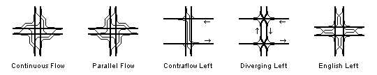
| Continuous Flow | Left turns cross oncoming traffic before the intersection. No extra phase needed. | Never | Never |
| Parallel Flow | Left turns cross oncoming traffic during cross street phase. No extra phase needed. | Never | Never |
| Contraflow Left | Left-turn lane placed to left of left-turn lane in opposite direction. | Never | Never |
| Diverging Lefts | Simultaneous green for one left turn from each street. | Never | Never |
| English Left | Left turns cross before intersection. All four lefts use the same phase. | Never | Never |
* The use of merge phases and channelization requires prohibiting turns on circular green or flashing yellow arrow. Even with flashing yellow arrows, yellow trap occurs in the change to a merge phase.
See this page for more on left-turn phases.
A dual left-turn signal has two left-turn phases. Both of the left-turn signals are on the same street. A dual ring controller is usually required. This setup usually needs five phases.
A quad left-turn signal has left-turn phases on all four approaches. A dual ring controller is usually required. This setup usually needs eight phases.
Yes. They have been improved over the years to make them safer and easier to understand. Here is a rough chronology:
- Circa 1920: The first left-turn phases were green or white arrows, without a change interval between the left turn and the thru movement on the same street.
- By the 1950s, the arrows were green, and signs determined whether the left turn was exclusively protected (LEFT ON ARROW ONLY) or protected/permissive (LEFT ON GREEN OR ARROW). Usually the change interval began with the green arrow being turned off, with no yellow indication to show the end of the phase (the "blind" change interval).
- In 1961, the MUTCD required a change interval before and after the left-turn phase, and provided that the exclusively protected left turn must have its own lane and a 3-lens signal with a green arrow.
- In 1971, red and yellow arrows were added to the MUTCD. The yellow arrow was used for the change interval, and the red arrow for a stop indication. The 5-section protected/permissive signal appeared.
- The 1978 MUTCD banned the blind change interval, requiring a yellow arrow to follow each green arrow.
- The 2003 MUTCD required yellow trap to be removed or warned with a sign, with a 2008 compliance date.
- The 2009 MUTCD added the flashing yellow arrow permissive turn indication as a means to prevent yellow trap.
A single half signal stops only one direction of traffic on the main street. It is used at T intersections where the thru movement on the side of the main street away from the side street need not be stopped. This signal can always provide perfect progression.
A dual half signal stops each direction of traffic on the main street independently of the other direction. It is used at Superstreet intersections. The advantage is that each half signal can be progressed independently of the other.
A deficient half signal stops one street for pedestrians, but does not control the other street at the intersection. A STOP sign usually controls the other street. It is prohibited by the MUTCD.
A direction-alternating signal stops one direction on the street, then lets that direction go while stopping the other direction. This is used for one-lane streets or bridges, temporary lane closures, and the diverging diamond interchange.
COORDINATION AND PROGRESSION
Coordination is used to cause many traffic signals to act with the same pattern, relative to each other, for each signal cycle. It is used to make signals able to handle more traffic by keeping one signal from blocking traffic released by another signal.
Signal coordination and signal synchronization are the same thing.
Progression is coordination of signals in a plan to time signals for traffic moving along one street so that the signals turn green as the platoons of cars come to them. Thus drivers traveling along that street do not have to stop at most of the lights.
See this page for more on progression.
Progression is actually very hard to achieve. The following factors enter into the decision:
- One-way streets are much easier to progress.
- Two-way streets are hard to progress in both directions. Often such progression is impossible.
- Often progression is attempted in only the direction with the heavier traffic at any one time.
- Short and varying signal spacings make progression much harder to achieve.
- The cycle length for optimum progression is often not the cycle length needed for the volume of traffic on the street.
- Progressing many parallel streets makes it harder to progress streets at right angles to those streets.
- Diagonal streets, curves, and changes in speed limits make progression harder.
- Left-turn signals on the cross street make progression much harder.
- Traffic actuation makes progression harder. There is often a choice between actuation and progression.
- The dual lead or dual lag left-turn signal sequences make progression harder.
- The lead-lag left-turn signal sequence can be used to make progression easier to achieve.
- The flashing yellow arrow signal makes progression easier by allowing a P/P lead-lag sequence.
- Progression cannot pass through an all-way stop, a roundabout, or an unsignalized interchange.
- Distances over a quarter mile allow the platoons of cars to break up, making progression harder.
- Traffic volumes might be too heavy for progression to work well, or too light to make progression worthwhile.
- Odd conditions in the area might make progression impossible (e.g. factory exit has sudden traffic surge).
- A grid of streets is extremely difficult to progress.
That works for an isolated one-way street. For two-way streets and street grids, it gets much more difficult:
- The ideal timings for one direction of travel do not work at all for traffic going the other way.
- When a pair of one-way streets is progressed, the cross streets at many places along those streets can not be progressed.
- When two streets at right angles to each other are progressed, no streets within a few blocks of those streets can be progressed.
- When signals are closely spaced together, two-way progression is impossible.
- Diagonal streets and curves can make progression impossible.
- Adding a signal demanded by the public in the wrong place can destroy existing progression.
 The time-space diagram is a tool used to design signal progression. One is shown here.
- Time is the vertical dimension. Time flows upward in the diagram.
- Distance along the street and between signals is the horizontal dimension. It is usually in seconds of travel time, so a change in the speed limit does not ruin the diagram.
- The vertical strips are the traffic signals. They are colored red at times when that signal is red.
- The green diagonal bands are through bands, showing how vehicles travel through the signals in time.
- The bands with arrows in them pointing in the direction of the bands are also through bands parallel to the green through bands.
The through band is the part of the cycle length where cars can follow the wave of green lights without stopping. Its value is usually given as a fraction of the cycle.
See this page for more on progression.
A platoon is a group of cars being progressed through coordinated signals. It is formed by the first signal, and ideally it stays together throughout the entire progression system.
The single-alternate system is the most commonly use progression system. As you look down the street, the lights alternate colors for adjacent blocks, e.g. red green red green....
The signals are spaced and the cycle length is set so that, as you approach each cross street, the signal turns green, while the next signal beyond that one and the signal behind you turn red. The time-space diagram shown above is a single-alternate diagram.
 The double-alternate system is used when the cross streets are too close together to use the
single-alternate system. It has a smaller through band than the single-alternate system. The signals
alternate in pairs, e.g. green green red red....
The double-alternate system is used when the cross streets are too close together to use the
single-alternate system. It has a smaller through band than the single-alternate system. The signals
alternate in pairs, e.g. green green red red....
This is the case where the lead-lag signal sequence becomes useful for progression. It can make up for the normally smaller through band. The time-space diagram shown to the right is a double-alternate diagram.
Note that the double-alternate system allows the use of the lead-lag left turn sequence to improve progression on the major street. The cyan parts of the signal strip show leading turns, while the yellow parts show lagging turns.
The simultaneous system has all of the signals on the street green at the same time. It can be used for streets with very long, but equal, distances between signals.
It is also used for coordination without progression where distances between signals are too short. This is often called the "rabbit system," because the traffic moves forward in jumps. In this case, the through band value is zero.
The best location depends on the type of signal:
- An ordinary signal works best near the locations marked A on the diagrams above.
- A signal with lead-lag left turns works best near locations marked B.
- Signals where the major route turns work best near locations marked C.
- Signals for high-volume diamond interchanges and diverging diamond interchanges work best near locations marked C.
Doubled signal strips are needed for locations marked C, since the signal is green in one direction when it is red in the other direction.
 The single-direction system is used on a one-way street, and when progression is impossible to achieve
in both directions. It has a larger through band than other systems. But on a two-way street, it causes
drivers going the other way have to stop more often, wasting gasoline.
The single-direction system is used on a one-way street, and when progression is impossible to achieve
in both directions. It has a larger through band than other systems. But on a two-way street, it causes
drivers going the other way have to stop more often, wasting gasoline.
Yes. Engineers develop different timing plans for different traffic conditions or for different times of the day. These are activated by time clocks, traffic adjusted control, analog computers, or digital computers.
Control systems for traffic adjusted control use detectors placed in strategic places on major streets to sample the traffic. They then choose traffic plans based on the observed traffic.
The principal problem is changing the signals from one plan to another. Progression is often disrupted during the actual changeover from one coordination plan to another. This means that the coordination plan for a heavy traffic period must be put in place before the heavy traffic actually begins, and it must stay in place until after the heavy traffic has ended.
The cycle length, split (division of signal time among phases), and offset (timing of the beginning of the green in the coordination plan) of each signal are usually different in each coordination plan. The problem is getting the signal to the new settings without seriously disrupting traffic. There are three methods:
- The main street green is extended until the new offset point is reached, then switching to the new setting. The controller essentially stops timing as soon as the main street turns green, and starts again when it reaches the correct offset. This prevents disruption of the main street, but causes unnecessary backups on the side streets.
- The offset interrupter is used to break the shift in the offset into small periods of 10 or 15 seconds. But this method destroys progression during the transition. Vehicles in platoons encounter red signals.
- The controller is set to a third cycle length to change the speed of the signal cycle until it catches up with the new plan: This has the same troubles the offset interrupter has.
TRAFFIC ACTUATION
One or more detectors are connected to each actuated phase. The detectors have two effects on the phase:
- If no traffic is waiting for the phase, the phase can be skipped. It will remain red.
- When the signal is green for the phase, it stays green until:
- Traffic lanes for the phase are empty (and any associated pedestrian signals have finished timing).
- A preset maximum time expires (when conflicting phases have detections).
In other words, the signal doesn't really look for cars, but the absence of cars. When cars are absent on one phase, the signal changes to a different phase with cars present.
There are several different methods:
- Large-area detection (loop or television) is used to monitor the lane for at least two seconds of approach for low speed (under 45 mph) approaches.
- A small detector placed 4 seconds back from the stop line of a high speed approach. The
controller provides two timing intervals:
- An initial period when the light turns green to clear out the number of cars that fit between the detector and the stop line
- An extension period added to the green for each car that crosses the detector while the signal is green.
- A small detector placed at least 4 seconds back from the stop line of a high speed approach. The
controller provides these timing intervals:
- An initial period when the light turns green to clear out the number of cars that fit between the detector and the stop line
- An extension period is added to the green for each car that crosses the detector while the signal is green. The extension time can be shortened after a preset interval if cars are waiting on other phases.
- A small detector placed at least 4 seconds back from the stop line of a high speed approach,
and a large-area detector covers the area just upstream of the stop line. The controller provides these
timing intervals:
- When the light turns green, the large area detector holds the green until the cars that are actually between the small detector and the stop line clear out.
- An extension period is added to the green for each car that crosses the small detector while the signal is green. The extension time can be shortened after a preset interval if cars are waiting on other phases.
These are settings to tell the signal how to use each detector.
- The locking setting remembers that a car was detected until it makes the signal turn green.
- The nonlocking setting forgets that a car was detected if the car leaves the detection area.
It's busy. The signal controller must do everything else that must be done before you get a green light. This includes all of the following:
- The signal that is already green must run out of cars, or reach the maximum setting.
- The phase that is green might not be actuated. If so, it has to stay green for its preset time.
- If the phase has pedestrian indications, both the Walk (white man) and Flashing Don't Walk (orange hand) periods must time out before the phase can end. These periods have fixed times.
- Your phase might not be next. The controller might have to serve several phases before it comes to yours. Other than phase skip, nothing can change the order of phases programmed into the controller.
- When the last phase before yours does end, the yellow and red change intervals must still be timed.
If the signal does change to green the moment your car is detected, the controller was resting.
When a traffic-actuated signal is not serving any traffic, it is resting. This means it is not timing any intervals. The last interval has already timed out, and no cars have arrived to start any new intervals. A setting on the controller selects how the controller rests. There are four kinds of resting:
- Rest on all phases red: After the last green interval ends, the signal times the yellow and red change intervals. All of the phases remain red until a vehicle is detected. The signal then immediately changes to green for the first phase with a detection.
- Rest on the last phase(s) used: That signal stays green until another phase has a detection. Then it times the yellow and red change intervals before changing to the phase with the detection.
- Major street green rest: After the last interval times out, the signal changes to the major street green. The major street phase stays green until traffic appears on another phase. Then the yellow and red change intervals are timed, and the signal changes to the occupied phase.
- Major street Walk rest: After the last interval times out, the signal changes to the major street green with walk. The major street phase stays green and in walk until traffic appears on another phase. Then the Don't Walk times out, followed by the yellow and red change intervals. After that, the signal changes to the occupied phase. This method has the slowest response.
- Major street green coordinated rest. The signal stays green on the major street until it receives the pulse from the coordination unit. This pulse releases it to change to other phases. When this happens, the controller times the yellow and red change intervals, and then services all of the other phases with actuations. After it finishes with the other phases, it again rests until it receives the coordination pulse. If no other phases are waiting to serve traffic, the major street signals stay green.
No. Detectors usually note only the presence or absence of vehicles, not their number or motion. And the signal must finish what it is doing before it changes to your phase.
This misconception probably arose from erratic behavior of earlier detectors. They failed to detect vehicles that stopped in certain places. Moving the vehicle moved it into an active location.
You can fool the signal into thinking you are not there by creeping up beyond the stop line. Then the detector can no longer detect you, and the signal forgets you were there.
There are several possible reasons:
- The most likely reason is that you stopped beyond the painted stop line, or crept up beyond it. If yours is the only car present, it is no longer in a detection zone. The signal thinks you turned on red, and forgets you, until another car comes along behind you.
- Protected/permissive left-turn phases might be set up to not show the protected green arrow unless three or more cars are waiting. This is possible with multiple loop detectors or a television detector. With these, you must make the permissive turn if there are not enough cars present.
- Some protected/permissive left-turn detectors have a delay of a few seconds before they place the call to the controller for the left-turn phase. During that period, the controller could advance past that phase.
- You could have arrived just after the coordination pulse. If so, the signal skipped your phase and went on to the next one. It got you the next time around.
- Your car might be one of the few that detectors can't find. Cars with very little metal in them will not actuate loop detectors. Also, some colors of paint are invisible to television detectors, because they match the road in infrared light.
- The detector may have been recalibrating after a change in weather (loop detector) or ambient lighting (television detector).
- The detector may be broken. But most loop detectors are designed so that a failure causes a permanent actuation.
- Some right turns are designed to be completed by right turns on red when other traffic is absent, and so have no detectors. This is a problem, because some trucking companies prohibit their drivers from making turns on red.
There are several possible reasons:
- The controller has locking detection and the car waiting for the phase turned right on red.
- A vehicle cut the corner and crossed the detector in the wrong direction.
- The detector was recalibrating itself after a change in weather (loop detector) or ambient lighting (television detector) and put out an actuation while it was unavailable.
- A truck in an adjacent lane triggered the detector even though the detector's lane was empty.
- A shadow from a vehicle in an adjacent lane triggered the television detector.
- The wind might have blown a television detector's mast arm enough to cause it to detect motion.
- The television detector may be misaimed. Strong winds can do this.
- The detector may be broken. Most loop detectors are designed so that a failure causes a permanent actuation.
These are the factors in pedestrian signal timing:
- The White Man lights long enough to get all of the waiting pedestrians into the crosswalk.
- The Flashing Orange Hand timing depends on the length of the longest crosswalk it serves.
- A period of Steady Orange Hand may follow the Flashing Orange Hand while the vehicle signal is still green so vehicles can turn.
- Some signals recall the pedestrian phase at certain times of the day, so the button does nothing during those times.
- Some signals give a longer pedestrian time with two pushes of the crossing button for people using walkers or crutches.
- Signals can shorten pedestrian intervals when emergency vehicles preempt the signal.
- If a pedestrian phase is associated with a vehicle phase, the vehicle phase cannot end its green interval until all of the pedestrian timing is complete, except in the case of a preemption.
- A pedestrian phase not associated with a vehicle phase can allow walk in all directions while all vehicle signals are red.
There are several reasons:
- Actuated signals cost more.
- Traffic actuation can disrupt signal progression (coordination).
- Some locations (e.g. truss bridges) are hard to actuate.
- Locations where different approaches belong to different governments need cooperation between governments.
Traffic adjusted control uses detectors to measure traffic volumes at various locations. The results are then used to select one of several coordination plans, rather than to change individual signals.
OVERLAP PHASES
A right-turn overlap is an overlap phase controlling a right turn that is a green arrow when either the straight-ahead phase from the same leg is green, or the left turn from the leg to the right is green.
Second yellow trap occurs when a permissive left turn is trapped on a yellow light by a green arrow shown to the opposing right turn as a right-turn overlap. This causes yellow trap even if the left turn uses a flashing yellow arrow. The traffic turning on the green right-turn arrow prevents the opposing left turn from clearing properly.
The following can prevent second yellow trap:
- Remove the right-turn overlap.
- Provide an island and receiving lane for right turn, to separate it from the receiving lane for the left turn.
- Instead of using an overlap phase, use a 5-section signal and wire the green and yellow arrows to the left-turn phase that the right turn overlaps.
- Give the trapped left turn an exclusively protected left-turn phase.
Third yellow trap is caused by a pedestrian phase that delays or inhibits a flashing yellow arrow phase when it is called by a pedestrian. Everything is safe unless the oncoming circular green phase is reserviced while green, to restart the pedestrian phase. If the flashing yellow arrow turns steady yellow, then red, for the reservice, while the parent phase stays green, third yellow trap occurs.
The following can prevent third yellow trap:
- Remove the delay or inhibition of the flashing yellow arrow. Use other methods to protect pedestrians.
- Prevent the phase from being reserviced while it is green or yellow.
- Prevent the flashing yellow arrow from changing to steady yellow arrow and red arrow during the reservice.
- Require the reserviced phase to change to yellow, then red, and hold for a several second red revert before reservicing it.
- Give the trapped left turn an exclusively protected left-turn phase instead of a flashing yellow arrow.
Little yellow trap is when the circular greens for both directions end at the same time, but the circular yellows do not.
When the shorter yellow turns red, the driver thinks the other direction is red too, and completes his turn. Although it is unlikely to happen, an oncoming straight-ahead driver could continue on through during this period, causing a crash.
Little yellow trap happens whenever the yellow clearance intervals of the two circular green phases are set to different values.
The following can prevent little yellow trap:
- Make sure the yellow clearance intervals on both circular green phases are set to the same value.
- If there are no turn arrows on the street, use the same phase unit for both circular greens.
Green trap occurs where there are no left turn phases, but the circular greens facing opposite directions can start at different times. This can fool a left turning driver when an opposing driver suddenly gets a circular green and starts to move.
In green trap, a left turning driver sees an oncoming car slowing down for a red signal, so he thinks he has the right-of-way. As the oncoming driver enters the detector, his signal suddenly turns green, and he speeds up to go straight or right. He enters the intersection in the path of the left turning vehicle. This can cause a crash.
Green trap happens when opposite circular greens on the same road have their own phase units, but no other phase units are in the concurrency group. The problem happens when one phase stays red until a car appears on the approach.
The following can prevent green trap:
- Use the same phase unit for both circular greens.
- Force display of concurrent greens.
SIGNAL CALCULATIONS
Use the following formula:
V = 3600 * S * (L / H) - C - P (in vehicles per hour)
(Same for metric)
Where:
V = Vehicles per hour
S = Split = Portion of the signal cycle the phase is green (entered as a fraction)
L = Number of lanes
H = headway in seconds per vehicle (2 for cars under 45 mph, 3 for cars over 45 mph, larger for heavy trucks).
P = 500 if parking is allowed along the right side of the right lane, 0 if not.
C = vehicles in conflict (veh/hr)
So a 2-lane approach with a 60% split, passenger cars at 30 mph, no conflicts, and no parking gives this result:
V = 3600 * 6/10 * (2 / 2) - 0 - 0 = 2160 veh/hr (vehicles per hour)
The dilemma zone is a dangerous section of roadway upstream from a traffic light that develops at higher speed. Within the dilemma zone, the driver seeing a yellow light has a problem:
- He doesn't have enough stopping distance to stop before entering the intersection.
- He can't keep going and clear the intersection before the light turn red.
Note these items:
- Adding to the problem is the fact that many people do not have the ability to quickly determine how far away the signal is. They are not sure what to do outside the dilemma zone.
- Some drivers have indecision, and wait too long to decide whether to brake or clear.
- The dilemma zone is different for different vehicle weights.
The following can be used to remove the danger of the dilemma zone:
- A long red change interval can prevent a collision with traffic from the next phase.
- A presignal (or distant signal) can be used to warn traffic of the upcoming light change.
- A detector can be used to extend the green until the dilemma zone is empty. Cannot be used with coordination.
- A standardized marker could be posted at the upstream end of the dilemma zone (at the speed limit) to help drivers determine whether or not to brake.
The distance between the stop line and the edge of the dilemma zone closest to the stop line is equal to the distance covered during the change intervals at the speed limit. Use this formula to find it:
d1 = 5280/3600 * s * (y + r) - w (in feet)
d1 = 1000/3600 * s * (y + r) - w (in meters)
Where:
d1 = Distance from stop line to the nearest edge of the dilemma zone (in feet, in meters)
s = Speed limit (in miles per hour, kilometers per hour)
y = Yellow change interval (in seconds)
r = Red change interval (in seconds)
w = Width of the intersection in the direction the car is traveling (in feet,
in meters)
The distance between the stop line and the edge of the dilemma zone farthest from the stop line is equal to the normal stopping distance at the speed limit. Use this formula to find it:
d2 = 5280/3600 * s * 1 + s2 / 30 / (f + g) (in feet)
d2 = 1000/3600 * s * 1 + s2 / 30 / (f + g) (in meters)
Where:
d2 = Distance from stop line to the farthest edge of the dilemma zone
s = Speed limit (miles per hour, kilometers per hour)
f = Coefficient of friction between tires and road (fraction)
g = Grade as the slope, where positive is a slope uphill
If d2 < d1, there is no dilemma zone.
So a level approach to a 40-foot intersection at 50 mph, with a 4-second yellow and no red change, and a coefficient of friction of 0.3, has a dilemma zone of:
d1 = 5280/3600 * 50 * (4 + 0) - 40 = 293.33 feet (near end)
d2 = 5280/3600 * 50 * 3/4 + 502 / 30 / (3.3 + 0) = 332.77 feet (far end)
The dilemma zone is 39.44 feet long.
Use the following formula to calculate the basic change interval:
y = 1 + s / (20 + 64.4 * g) (in seconds - English)
y = 1 + s / (6.09 + 19.6 * g) (in seconds - metric)
r = (w + l) / s (in seconds - English)
c = (w + l) / s (in seconds - metric)
Where:
y = Yellow change interval in seconds
r = red change interval in seconds
s = Speed limit in feet per second (multiply miles per hour by 5280/3600)
s = Speed limit in meters per second (multiply kilometers per hour by 1000/3600)
g = grade (slope of intersection, + = uphill, -- = downhill)
w = width if the intersection (in feet, meters)
l = length of vehicle (in feet, meters)
On a level 30 mph street with a 40 foot intersection, a 15 foot car, the basic change interval is:
y = 1 + 44 / (20 + 0) = 3.2 seconds
r = (40 + 15) / 44 = 1.25 seconds
Normally change intervals calculated above are used. But there are exceptions:
- If the yellow change interval is shorter than 3 seconds, the yellow change interval must be lengthened to 3 seconds to satisfy the MUTCD.
- If the yellow change interval is longer than 6 seconds, the yellow change interval must be set to 6 seconds. The red change interval must be set to the remainder of the yellow change interval plus the red change interval to satisfy the MUTCD.
- If a dilemma zone exists, the total change interval must be long enough to prevent a crash from a confused motorist.
Use the following formula to find optimum signal spacing for a given speed and cycle length:
d = 5280/3600 * s * C / k (in feet)
d = 1000/3600 * s * C / k (in meters)
d = Distance between signals (in feet, meters)
s = Speed (in miles per hour, kilometers per hour)
C = Cycle length in seconds
k = Progression type: 1 = simultaneous, 2 = single alternate, 4 = double alternate
On a 30 mph street with a 60 second cycle length, the spacings should be:
5280/3600 * 30 * 60 / 1 = 2640 feet, for simultaneous signals
5280/3600 * 30 * 60 / 2 = 1320 feet, for single alternate
5280/3600 * 30 * 60 / 4 = 660 feet, for double alternate
Use the following formula to find the optimum speed for a given signal spacing and cycle length:
s = 3600/5280 * d * k / C (in mph) Use the definitions above.
s = 3600/1000 * d * k / C (in Kmph) Use the definitions above.
On a street with a 60 second cycle length, and spacings of 1320 feet, the speed should be:
3600/5280 * 1320 * 1 / 60 = 15 mph, for simultaneous
3600/5280 * 1320 * 2 / 60 = 30 mph, for single alternate
3600/5280 * 1320 * 4 / 60 = 60 mph, for double alternate
Use the following formula to find the optimum cycle length for a given signal spacing and speed:
C = 3600/5280 * d * k / s (in seconds) Use the definitions above.
C = 3600/1000 * d * k / s (in seconds) Use the definitions above.
On a 30 mph street with spacings of 1320 feet, the cycle length should be:
3600/5280 * 1320 * 1 / 30 = 30 seconds, for simultaneous
3600/5280 * 1320 * 2 / 30 = 60 seconds, for single alternate
3600/5280 * 1320 * 4 / 30 = 120 seconds, for double alternate
The following are methods used to reduce the number of signal phases needed, usually by the removal of left-turn phases:
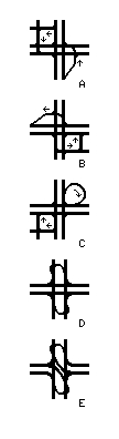 Diverting left turns:
- Use Jughandle roads to divert turns from the intersection. A jughandle turns right before the intersection, then turns left onto the cross street (A, at right).
- Use Reverse Jughandle roads to divert turns from the intersection. A reverse jughandle turns left after the intersection, then turns right onto the cross street after the intersection (B, at right).
- Use Cloverleaf Jughandle roads to divert turns from the intersection. A cloverleaf jughandle turns right after the intersection, then turns right onto the cross street before the intersection (C, at right).
- Use existing streets to form jughandle, reverse jughandle, or cloverleaf jughandle turn diversions (the squared connections in A, B, and C, at right).
- Prohibit one or more left turns, making drivers find their own diverted turn routes.
- Build a Continuous Flow Intersection (see below).
- Build a Parallel Flow Intersection (see below).
- Put in Michigan Left Turns (D, at right).
- Build a Single Quadrant Roadway or use an existing street, and divert all left turns to it.
- Diverting other movements:
- Prohibit or divert cross street traffic.
- Build a Michigan Left Intersection with no crossroad median gap. Use half signals at the side streets and the turnbacks.
- Build a Superstreet Intersection. Use a dual half signal at the intersections and half signals at the turnbacks (E, at right).
- Braid turning traffic lanes:
- Build an English Left Intersection. One phase controls all four left turns (below).
- For one-way cross streets, build a pair of contraflow left intersections (below).
- For one-way cross streets, build a pair of diverging left intersections (below).
- Other measures:
- Make some streets into one-way pairs. This reduces the number of left-turn phases needed.
- Close a street. Divert its traffic to other streets.
- Replace the intersection with a roundabout.
There are several reasons:
- The roundabout needs more real estate and more pavement than a traffic light intersection. Thus, it costs more.
- The use of eminent domain to obtain the land could also incur government attorney and court costs.
- In many locations existing buildings would have to be torn down to build roundabouts. So roundabouts are better suited to new developments, rather than most existing intersections.
- Roundabouts are best suited to single lane approaches. Multiple-lane roundabouts are harder for drivers to negotiate successfully. Passing and lane changes within the circular roadway can cause crashes. Multiple-lane roundabouts also need much more land and pavement than single lane roundabouts.
- Traffic signals can handle higher total volumes than roundabouts, so roundabouts are not useful at very high volume intersections. One exception is where a roundabout is used to divert left turns from a high-volume intersection.
- If the volume is too high for a traffic signal, a grade-separated interchange is needed.
- A roundabout disrupts signal progression. The platoons are broken up when they pass through a roundabout.