LINE VOLTAGE CIRCUITS FOR SELECTING
BETWEEN SERIES OR PARALLEL OPERATION
OF LAMPS AND IMPEDANCES

Line Voltage Light Bulb Circuits

The following circuits are the line voltage circuits that can be used for line voltage uses. They can be used for photoflood lighting circuits, keeping the screw shell of a line-voltage operated lamp on the neutral side in case the bulb is removed. The requirement of polarized plugs with the screw shell connected to the neutral blade is technically met.

These circuits must never be used with compact fluorescent lamps or light emitting diode lamps.

Here is a list of the loads commonly switched with these circuits, and the constraints each kind imposes on the design:

The SEPAR circuit numbers used here have been used by the page author for years to catalog the various circuits.

The SP-STD circuit numbers are new designations by the page author for new circuits.

The following variations are permitted when line voltage lamps are used in series-parallel switching circuits.

The same circuits can be used for switching impedances and polarized heating elements.

RULES FOR LINE VOLTAGE SERIES-PARALLEL CIRCUITS

- The power to the entire unit must be turned off before any bulbs are changed.

- If the lamps are connected by cords and plugs, all of them must always be plugged in.

- If lamps must be unplugged, plug in dummy loads to load the circuit.

- If there are switches on the lampholders, they must never be turned off.

 Failure to obey these rules can possibly expose someone changing a bulb to lethal voltage.

BEST USE OF LINE VOLTAGE SERIES-PARALLEL CIRCUITS

- The switch positions on the STD units are intuitive:
    - Both ON (up) - The outputs are in parallel.
    - Left ON Right DIM - Left is ON, Right is off.
    - Left DIM Right ON - Left is off, Right is ON.
    - Both DIM (down) - The outputs are in series.

- The wattages of the bulbs should be the same, so all bulbs in series are the same brightness.

- If STD units are cascaded, the tree form is better than the linear cascade if quick dimming is needed.

- If STD units are cascaded, the linear form is better than the tree cascade if some favored-lamp series-parallel switchings are needed.

- If STD units are cascaded in tree form and the same number of lamps is on each side of the tree, then the switches on the top-level unit can be used to quickly dim all of them. This also helps even out wattage differences if the wattages are not all identical.

- The SWAP BOX can't swap the power feed to any specific device with a device that gets power from that specific device.

KEY TO TABLE ENTRIES

ON
  - Connected directly to power

DIM
  - 2 or 3 lamps in series
  - series in a series-parallel

Glim
  - 4 or more lamps in series
  - parallel in a series-parallel

off
  - No current through lamp


  - Switch position unimportant

*
  - All possible displays shown.
  - Redundant combos not shown.


  - Settings for photofloods

Letters indicate closed switches.

No letter for a switch, or an o for a switch, means the switch is open, or is in the unlabeled position.

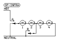
  • SEPAR 203 and SEPAR 204 (A circuit the page author built in 1984 and modified in 2004)

    SEPAR 203
    SWITCHLAMP
    AB C12
    oooffoff
    oBDIMDIM
    oCoffON
    AoONoff
    ABONoff
    ACONON

    This Series-Parallel Switching Circuit was originally built to put two electric fans in series or parallel, or to turn on either fan alone, for ventilation speed control. All possible combinations of series and parallel are possible, including off. Notice how one load can be connected to the live phase without any ground connection. This circuit is not safe for line voltage use.

    A later version of this series-parallel switching circuit (SEPAR 204) was built to conform to the requirements of line voltage circuits. The switch positions are exactly the same, but the live connections are removed if the neutral side is opened.

    Note that any switch position with a letter on it is the position indicated by that letter in the table.

  • SP-STD 2 (Built by page author in 2013)

    SP-STD 2
    SWITCHLAMP
    AB12
    DIMDIMDIMDIM
    DIMONoffON
    ONDIMONoff
    ONONONON

    Designed by the page author while playing with SEPAR 204 diagram on paper. It provides all possible combinations.

    This circuit never removes the neutral from a lamp except when the lamp is in series, or momentarily while a switch is being thrown. The mark under each lamp in the diagram indicates the lead connected to the screw shell of the lamp.

    Note that no OFF position is available. This makes the circuit useful for cases where the circuit must never be left open. If an off position is needed, an optional POWER switch can be connected in the live phase line as shown.

    This circuit can replace the SEPAR-201 or SEPAR-202 units for photoflood purposes. If a power switch is needed, add it into the HOT lead as shown.

  • SP-STD 3 (Two SP-STD 2 circuits cascaded)

    SP-STD 3
    SWITCH
    LAMP
    ABCD
    123
    DIMDIMDIMDIM
    DIMDIMDIM
    DIMDIMDIMON
    DIMoffDIM
    DIMDIMONDIM
    DIMDIMoff
    DIMDIMONON
    DIMGlimGlim
    DIMONDIMDIM
    offDIMDIM
    DIMONDIMON
    offoffON
    DIMONONDIM
    offONoff
    DIMONONON
    offONON
    ONDIM
    ONoffoff
    ONONDIMDIM
    ONDIMDIM
    ONONDIMON
    ONoffON
    ONONONDIM
    ONONoff
    ONONONON
    ONONON

    This is two SP-STD 2 units cascaded. It provides all possible series combinations and all parallel combinations, plus one series-parallel combination and one parallel-series combination.

    This circuit can replace the SEPAR-302 or SEPAR-305 units for photoflood purposes. If a power switch is needed, add it into the HOT lead as shown at left.

  • SP-STD 4 (Three SP-STD 2 units in tree form)

    SWITCH
    LAMP
    SWITCH
    LAMP
    ABCDEF
    1234
    ABCDEF
    1234
    DIMDIMDIMDIMDIMDIM
    GlimGlimGlimGlim ONONDIMDIMDIMDIM
    DIMDIMDIMDIM
    DIMDIMDIMDIMDIMON
    DIMDIMoffDIM
    ONONDIMDIMDIMON
    DIMDIMoffON
    DIMDIMDIMDIMONDIM
    DIMDIMDIMoff ONONDIMDIMONDIM
    DIMDIMONoff
    DIMDIMDIMDIMONON
    DIMDIMGlimGlim
    ONONDIMDIMONON
    DIMDIMONON
    DIMDIMDIMONDIMDIM
    offDIMDIMDIM
    ONONDIMONDIMDIM
    offONDIMDIM
    DIMDIMDIMONDIMON
    offDIMoffDIM
    ONONDIMONDIMON
    offONoffON
    DIMDIMDIMONONDIM
    offDIMDIMoff
    ONONDIMONONDIM
    offONONoff
    DIMDIMDIMONONON
    offDIMGlimGlim
    ONONDIMONONON
    offONONON
    DIMDIMONDIMDIMDIM
    DIMoffDIMDIM
    ONONONDIMDIMDIM
    ONoffDIMDIM
    DIMDIMONDIMDIMON
    DIMoffoffDIM
    ONONONDIMDIMON
    ONoffoffON
    DIMDIMONDIMONDIM
    DIMoffDIMoff
    ONONONDIMONDIM
    ONoffONoff
    DIMDIMONDIMONON
    DIMoffGlimGlim
    ONONONDIMONON
    ONoffONON
    DIMDIMONONDIMDIM
    GlimGlimDIMDIM
    ONONONONDIMDIM
    ONONDIMDIM
    DIMDIMONONDIMON
    GlimGlimoffDIM
    ONONONONDIMON
    ONONoffON
    DIMDIMONONONDIM
    GlimGlimDIMoff
    ONONONONONDIM
    ONONONoff
    DIMDIMONONONON
    DIMDIMDIMDIM ONONONONONON
    ONONONON
    ABCDEF
    1234
    ABCDEF
    1234
    DIMONDIMDIM
    offoffDIMDIM
    ONDIMDIMDIM
    DIMDIMoffoff
    DIMONDIMON
    offoffoffON
    ONDIMDIMON
    offONoffoff
    DIMONONDIM
    offoffONoff
    ONDIMONDIM
    ONoffoffoff
    DIMONONON
    offoffONON
    ONDIMONON
    ONONoffoff

    This is three SP-STD 2 units cascaded in tree form. It provides all possible series combinations and all parallel combinations, plus some series-parallel and parallel-series combinations.

    This circuit can replace the SEPAR-401 or SEPAR-402 units for photoflood purposes. If a power switch is needed, add it into the HOT lead as shown above.

    Note: If four lamps are always used for photofloods, the ALT diagram (lower right) shows the use of two separate SP-STD 2 units.

    SP-STD 4
  • SP-STD SWAP SWITCH

    SP STD SWAP

    The swap switch can be inserted into two hot-neutral pairs to trade the loads on these pairs

    SWAP
    SWITCH
    OUTPUTS
    12
    o12LAMPS
    SWAP21

    All possible series combinations and all possible parallel combinations can be switched with any of these circuits.

    A

    Diagram A is designed to put any of the three lamps into the master position (on switch A) for use with series-parallel and parallel-series switching.

    SWAP SWITCHOUTPUTS
    PQ123
    oo123 L
    A
    M
    P
    S
    Po213
    oQ132
    PQ312

    B

    Diagram B is designed to put any of the three lamps into any possible series order on the SP-STD 3.

    SWAP SWITCHOUTPUTS
    PQR123
    ooo123 L
    A
    M
    P
    S
    Poo213
    oQo132
    PQo312
    ooR132
    PoR231
    oQR123
    PQR321

    C

    Diagram C is designed to group any of the four lamps into pairs on the lower SP-STD 2 units in the tree structure for use with series-parallel and parallel-series switching.

    SWAP SWITCHOUTPUTS
    PQ1234
    oo1234 L
    A
    M
    P
    S
    Po1324
    oQ1243
    PQ1423
  • SP-STD SETS: Assembling larger sets from the SP-STD 2 units.

    SP STD SETS

    The following are larger circuits compounded from the basic SP-STD 2.
       D. 4 lamps cascaded
       E. 5 lamps unbalanced tree
       F. 5 lamps cascaded
       G. 5 lamps unbalanced tree reversed
       H. 6 lamps unbalanced tree
       I. 6 lamps balanced tree
       J. 7 lamps unbalanced tree
       K. 7 lamps cascaded

    All possible series combinations (within a set series order) and all possible parallel combinations can be switched with any of these circuits. They can also be combined with SWAP switches on any pairs of lamps, as shown above.

    Epilog: The page author has since proved that it is impossible to make a switching circuit that can provide all possible combinations of series and parallel and that is also polarity-safe (never reverses lamp polarity) and neutral-safe (never connects lamp to hot without a path to a neutral connection).

  • SP-STD Cord and plug modules

    SP STD Cord and Plug SP Infrared control

    A. The STD BOX is the SP-STD 2 switching circuit fitted with cords, plugs, and sockets.

    B. The SERIES CORD always places two devices in series.

    C. The SERIES BOX switches between two loads in series and one load operating alone.

    D. The CUBE TAP is an ordinary multiple outlet adapter.

    E. The SWAP BOX exchanges two loads.

    F. The SP-INFRA BOX is like the series box, except each load is a series of two lamps.
    This provides a low-level infrared augmentation.

    SERIES BOX OPERATION
    SWITCHOUTPUTS
    POWERSERIES12
    ooffoff
    ONSERDIMDIM
    ON1ONoff

    SPECIAL RULES FOR CORD AND PLUG LINE VOLTAGE SERIES-PARALLEL CIRCUITS

    - The SWAP BOX can't swap the power feed to any specific device with a device that gets power from that specific device.

    - If portable heaters are connected in series to reduce power consumption, make sure any fans in those heaters are rotating.

    - If portable heaters are connected in series to reduce power consumption, make sure any fans in those heaters keep rotating if changes are made in the settings of those heaters.

      SPECIAL RULES IF LAMPS WITH SCREW-SHELL SOCKETS ARE USED IN THE SETUP:

      - The only power ON/OFF switch allowed in any setup of these units must be on the power feed to the first unit.

      - Power to the entire setup must be off before any bulbs are changed.

      - Power to the entire setup must be off before the setup is reconfigured.

      - All devices must always be plugged in when the power is on.

      - If a device must be unplugged, plug in a dummy load to load the circuit.

      - If there are switches on devices, they must never be turned off.

       Failure to obey these rules can possibly expose someone changing a bulb to lethal voltage.

        BEST USE OF CORD AND PLUG LINE VOLTAGE SERIES-PARALLEL CIRCUITS

      - The wattages of devices should be such that all of them can operate.

      - If STD BOXES are cascaded, the tree form is better than the linear cascade if quick dimming is needed.

      - If STD BOXES are cascaded, the linear form is better than the tree cascade if some favored-lamp series-parallel switchings are needed.

      - If STD units are cascaded in balanced tree form and the same number of loads is on each side of the tree, then the switches on the top-level unit can be used to quickly dim all of them. This also helps even out wattage differences if the wattages are not all identical.


LINKS:

  1. SELECTING SERIES OR PARALLEL OPERATION (Main Page)
  2. LIGHT BULBS, SPECTRA, and HUMAN VISION
  3. Computers, Science, and Measurement