CIRCUITS FOR SELECTING
BETWEEN SERIES OR PARALLEL OPERATION
OF GUITAR PICKUPS

Guitar Pickup Circuits

Switching circuits for guitar pickups have purposes that are different from those for switching loads. The purposes are:

  1. Providing signal to a guitar amplifier.
  2. Making sure the line to the amplifier is never open.
  3. If a pickup is to be muted, disconnect it or short it out.

Here is a list of the constraints guitar pickups impose on the design:

The SEPAR circuit numbers used here have been used by the page author for years to catalog the various circuits.

The SP-STD circuit numbers are new designations by the page author for new circuits.

The following variations are permitted when guitar pickups are used in series-parallel switching circuits.

Note that, to conserve website server storage space and bandwidth, some of the following diagrams show light bulbs instead of guitar pickups because they are the same diagrams used on the lightbulb pages. Let the end of the light bulb with the extra arc showing the screw shell be the ground or negative polarity terminal of the pickup.

Examples:

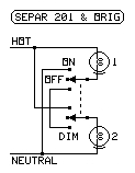
SEPAR 201
  • The Original Series-Parallel Switchbox for Two pickups.

    This has been used for pickups for a very long time.

    The center OFF position must be eliminated to prevent hum.

    The negative side of the pickup is denoted by the screw shell mark on the lamp in the image.

    Remember that guitar pickups are substituted for the lamps shown in the diagrams.

KEY TO TABLE ENTRIES

ON
  - Connected directly to output
     (label this switch position
     "PARALLEL")

DIM
  - In series with other pickups
     (label this switch position
     "SERIES")

PAR
  - In parallel with other pickups
     (label this switch position
     "PARALLEL")

SER
  - In series with other pickups
     (label this switch position
     "SERIES")

B
  - Position for the bridge pickup

N
  - Position for the neck pickup

C
  - Position for both pickups

off
  - Pickup not connected to output


  - Switch position unimportant

Letters indicate closed switches.

No letter for a switch, or an o for a switch, means the switch is open, or is in the unlabeled position.

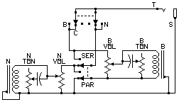
  • SP-PIC 2 (Seen on some guitars)

    SP-PIC 2
    SWITCHPICKUP
    S-PB-NBN
    SER-SERSER
    PARBONoff
    PARCPARPAR
    PARNoffON

    This uses the existing pickup switch (bridge, both, neck) and a double-pole switch for series and parallel. Each pickup is either grounded or in series with a grounded pickup.

    Note that the pickup switch does not do anything in the series position. It can be preset for the next pickup configuration wanted.

    This example has individual volume and tone controls that work in series or in parallel.

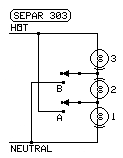
  • SEPAR 303

    SEPAR 303 (Page author, 1963)

    SWITCHPICKUP
    A B123
    oSERSERSER
    A BPARPARPAR

    Should be built with one double-pole switch to keep the hot side from having two pickups hanging from it (causes hum).

    Note that the middle pickup is phase reversed in the series position. The page author has seen this circuit on guitars. The unique sound in the series position is caused by the middle pickup being phase-reversed to the neck and bridge pickups for a special effect.

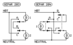
  • SEPAR 204

    SEPAR 204
    SWITCHPICKUP
    AB C12
    oBSERSER
    oCoffON
    ABONoff
    ACPARPAR

    The SEPAR 204 Series-Parallel Switching Circuit can use either pickup alone, both in series, or both in parallel. Do not use SEPAR 203 with guitar pickups.

    A special version of SEPAR 204 must be used with no center-off position on switch B C). The other switch positions are the same. The hot connections on a pickup are removed if the ground side is opened.

    Note that any switch position with a letter on it is the position indicated by that letter in the table.

    Remember that guitar pickups are substituted for the lamps shown in the diagrams.

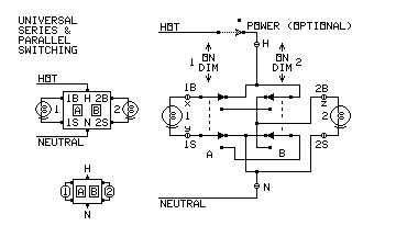
  • SP-STD 2 (Built by page author in 2013)

    SP-STD 2
    SWITCHPICKUP
    AB12
    DIMDIMSERSER
    DIMONoffON
    ONDIMONoff
    ONONONON

    This circuit provides all possible combinations except all off.

    This circuit never removes the negative connection from a pickup except when the pickup is in series, or momentarily while a switch is being thrown.

    Remember that pickups are substituted for the lamps shown in the diagrams. The mark under each "lamp" in the diagram indicates the negative phase terminal of the pickup.

    Note that no OFF position is available. Do not include the power switch shown in the diagram (it would cause hum).

    The pickups always maintain the same phase with this setup.

    The switch should be labeled with PARALLEL for ON, and SERIES for DIM.

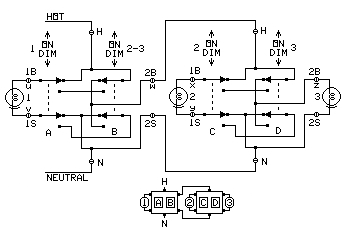
  • SP-STD 3 (Two SP-STD 2 circuits cascaded)

    SP-STD 3
    SWITCH
    PICKUP
    ABCD
    123
    DIMDIMDIMDIM
    SERSERSER
    DIMDIMDIMON
    SERoffSER
    DIMDIMONDIM
    SERSERoff
    DIMDIMONON
    SERS-PARS-PAR
    DIMONDIMDIM
    offSERSER
    DIMONDIMON
    offoffON
    DIMONONDIM
    offONoff
    DIMONONON
    offPARPAR
    ONDIM
    ONoffoff
    ONONDIMDIM
    PARP-SERP-SER
    ONONDIMON
    PARoffPAR
    ONONONDIM
    PARPARoff
    ONONONON
    PARPARPAR

    This is two SP-STD 2 units cascaded.

    Remember that pickups are substituted for the lamps shown in the diagram.

    The extra mark indicates the negative phase lead.

    The switch should be labeled with PARALLEL for ON, and SERIES for DIM.

    This setup provides all series and all parallel combinations, plus one parallel-series combination and one series-parallel combination.

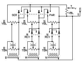
  • SP-PIC 3

    SP-PIC 3

    This is a circuit that places three pickups in series or parallel with one switch.

    Each pickup has a volume and tone control. These controls are arranged to affect only the pickup they are connected to.

    A pickup can be totally removed from the output by turning it all the way down.

    A master volume control adjusts the overall output level.

    Phase reverse switches are provided for the neck and mid pickups.


LINKS:

  1. SELECTING SERIES OR PARALLEL OPERATION (Main Page)
  2. LIGHT BULBS, SPECTRA, and HUMAN VISION
  3. Computers, Science, and Measurement