INNOVATIVE ELECTRICAL APPLICATIONS

Here are some unusual uses for common electrical devices:

To enlarge an image, right click and view image. Then use Ctrl(+) to enlarge.


A Feet Warmer

The concrete floor was cold, so I wanted a heater to keep my feet warm under a workbench. I tried a standard portable heater, but it had two problems:

  1. The standard heater's thermostat alternately roasted and froze my feet.
  2. The standard heater could not be used when I used the soldering iron at the same workbench or the circuit breaker would trip.

The problem is that nobody sold a heater that puts out less than 500 watts. So I made one:

The calculations I used are as follows:

Heater calculations:

Calculations at 240 Volts:

500 W / 240 V = 2.0833 A

240 V / 2.0833 A = 115.2 Ω
 

This heating element is ohmic, meaning it does not change resistance with changes in temperature.
 

Calculations at 120 Volts:

120 V / 115.2 Ω = 1.0417 A

120 V × 1.0417 A = 125 W
 

125 W = 125 J/s

cv,air = 1 KJ/Kg/°C

cbed = 20 KJ/bed/°C

Warmer temp = Tht = 116°F = 46.7°C

Over the warmer temp = Toh = 99°F = 37.2°C

Ambient air temp = Tam = 80°F = 26.7°C

Mattress temp = Tmt = (Tam + Toh) / 2

Tmt = (80°F + 99°F) / 2

Tmt = 89.5°F = 31.9°C

Tambient °F 68.072.076.080.084.0
Tambient °C 20.022.224.426.728.9
Tmattress °F 83.585.587.589.591.5
Tmattress °C 28.629.730.832.033.1


CPSC SPACE HEATER STANDARD USUALLY CAN'T BE OBEYED

The CPSC rule requires a circle of empty space at least 6 feet in diameter with the heater in the center.

Very few places have such a space available. Most homes could not have even half of that space available.

This seems to be an overkill standard with parameters chosen by bureaucrats to keep space heaters from being used.

The standard was designed for the worst case (1500 Watt heater), but written to be a one-size-fits-all standard. It is overkill for small heaters.

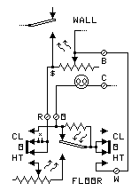
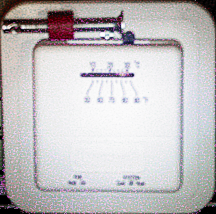
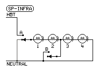
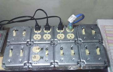
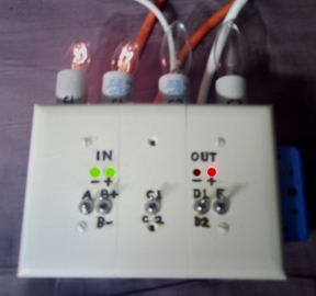
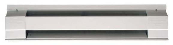
I bought a 500 watt 240 volt baseboard heater and put a 120 volt plug on it, as shown at right. Make sure the hot wire goes to the thermal fuse.

The calculations show that the heater is now a 125 watt warmer.

This warmer does not draw enough current to cause problems when the soldering iron was in use.

The warmer worked just as I wanted it without a thermostat.

When I later wanted to adjust this kind of warmer's output, I found that an ordinary lamp dimmer worked quite well.

The thermal fuse prevents the warmer from overheating.

Because of the shape of the case, I had to use the warmer upside down so it could be set flat on the floor.

desk warmer

Wiring diagram of a 240 V
500 W heater connected as
a 125 W 120 V warmer

This can also be used under a bed, as it does not make enough heat to cause a hazard

  • There is an air space between the warmer and the bed.
  • The free-air temperature is too low to overheat or ignite anything:

    The highest temperature this warmer produces in free air is 116°F (47°C) - Empirically measured.

    1. The span of temperatures for electric blankets is 64°F to 133°F (18°C to 56°C).
    2. The air temperature of a floor register under bed reaches 133°F (56.1.4°C).
    3. The temperature of a sample 400 W space heater reached 175°F (79.4°C).
    4. The temperature of a sample 750 W space heater reached 188°F (86.7°C).
    5. The temperature of a sample 1500 W space heater reached 255°F (123.9°C).
    6. The top safe temperature for hot water to prevent scalding is 120°F (48.8°C).
    7. The lowest ignition temperature of household detritus is 450°F (232.2°C).
    8. The highest air temperature this warmer can produce is 119°F (48.3°C) empirically measured.

    This warmer's temperature is lower than any of these listed temperatures.

  • There is no possible way this warmer can produce a higher temperature unless:
    1. The line voltage increases substantially above 120 V.
    2. The warmer is physically smashed, causing a partial short circuit.
  • The power dissipation of this warmer is spread over a wide area.
    1. The element is a 30-inch tube with a 1-inch circumference.
    2. The power density of the warming element is 125W / (30in×1in) = 4.17 watts per inch.

DEFINITIONS:

Joule (J) - The metric unit of energy.

1 joule = 1 watt second

cv = Coefficient of specific heat

cv,air = 1 KJ/Kg/°C

This means that it takes 1000 joules of heat to increase the temperature of a kilogram of air by 1°C.

About 1 Kg of air is under a bed.

cv,bed = 20 KJ/bed/°C

This means that it takes 20000 joules of heat to increase the temperature of the bed by 1°C.

The entire bed is the thermodynamic element.

The 20 KJ is an average.
 

Cadet heater

CONVERTED
CADET HEATER

- Power used: 125 W
- Max temperature: 119°F
- Case is not hot to the touch.
- Use anywhere.

COMPARE TO
ELECTRIC BLANKET

- Power used: 200 .. 400 W
- Max temperature: 133°F
- No objects on top of blanket.

COMPARE TO
FLOOR WARMING MAT

- Power used: 120 W
- Max temperature: 150°F
- Case is not hot to the touch.
- Use anywhere.


Using 120V incandescent lamps as loads in 24V circuits

In the following circuits, 120V lamps are used in 24V circuits. Here are the calculations for doing this:

Lamp Value Table

Lamp
W
A @
120V
Ω @
120V
Ω @
24V
A @
24V
W @
24V
3.02504800 1344.01790.429
6.05002400 672.03570.857
10.08331440 403.05951.43
15.125960 269.08932.14
25.208576 161.1493.57
40.333360 101.2385.71
60.500240 67.2.3578.57

Incandescent lamps are non-omic. Their resistances increase linearly as their temperatures increase.

Here is the procedure for calculation:

  1. Divide actual voltage by rated bulb voltage for ratio (24 / 120 = .2).
  2. Find R factor: Multiply ratio by 0.9 and add 0.1 (.2 × .9 + .1 = .28)
  3. Divide the lamp wattage by 120V to get the 120V amperage A.
  4. Divide 120V by 120V amperage A to get 120V resistance Ω.
  5. Multiply 120V resistance by R factor to get 24V Resistance
  6. Divide 24V by 24V resistance Ω to get 24V amperage A.
  7. Multiply 24V by 24V amperage A to get actual 24V wattage W.

Note that the cold resistance of a lightbulb is approximately 1/10 the hot resistance. This table assumes that value. For more accuracy, measure the cold resistance.

Because a single
lightbulb is discussed,
there is no schematic.


A Floor Warmer

The floor is cold in the house when the weather is colder outside, so I wanted a way to make the furnace run longer per cycle when the floor is cold, rather than having to monkey with the thermostat when the weather changes.

From the table above, these lamps
are useful:

Lamp
W
A @
120V
Ω @
120V
Ω @
24V
A @
24V
W @
24V
3.02504800 1344.01790.429
6.05002400 672.03570.857
10.08331440 403.05951.43

The light bulb is optional. Its purpose is to make the anticipator on the floor thermostat operate. Use a 120 V bulb between 3 W and 10 W, and keep it away from the thermostats.

I bought a second thermostat and mounted it just above the baseboard at floor level. I used a Honeywell CT31 A1003 with a slotted cover over it to protect it from foot traffic. These thermostats must be simple thermostats, not electronic ones.

I connected the heat connections of the floor thermostat to the terminals across the anticipator heater of the other thermostat, as shown in the diagram.

The connection marked $ has no screw terminal and must be soldered. Also, cut the jumper at x.

Set the floor thermostat 2 to 4 degrees below the setting on the wall thermostat.

Set the wall anticipator for normal operation. Set the floor anticipator experimentally to get the amount of extra heat needed.

To enable the floor thermostat, set its switch to HEAT.
To disable it, set its switch to OFF.

floor booster

The two switches shown are ganged.


Another Floor Warmer

The floor is cold in the house when the weather is colder outside, so I wanted a way to make the furnace run a little short cycle to pull the cold air off the floor and heat it.

The return register must be on the floor. This will not work if the return registers are on the ceiling.

I bought two identical thermostats.

I mounted the wall thermostat in the usual place. I mounted the return thermostat near the return air register.

These thermostats must be simple thermostats, not electronic ones.

I connected the heat connections of the return thermostat in parallel with the heat connections of the wall thermostat.

Set the return thermostat 1 to 3 degrees below the setting on the wall thermostat.

Set the wall anticipator for normal operation.

Set the return anticipator for the shortest possible burn time that will start the fan.

Do not set both anticipators to the same values. This will cause alternating extremely hot periods and extremely cold periods.

To enable the return thermostat, set its switch to HEAT.
To disable it, set its switch to OFF.

floor booster 2

Another Floor Warmer Improved

The floor is cold in the house when the weather is colder outside, so I wanted a way to make the furnace run a little short cycle to pull the cold air off the floor and heat it. This is improved from the one above.

The floor thermostat must be on the floor or the baseboard. This will not work if the return registers are on the ceiling.

I bought two identical thermostats.

I mounted the wall thermostat in the usual place. I mounted the floor thermostat near the floor return air register.

These thermostats must be simple thermostats, not electronic ones.

I connected the heat connections of the floor thermostat to the wall thermostat as shown in the diagram.

Set the floor thermostat 1 to 3 degrees below the setting on the wall thermostat.

Set the wall anticipator for normal operation.

Set the floor anticipator for the shortest possible burn time that will start the fan.

Do not set both anticipators to the same values.

To enable the floor thermostat, set its switch to HEAT.
To disable it, set its switch to OFF.

floor booster 3

An Air Stirrer

The air in the house gets stratified. Also, the air needs to be run through the high efficiency filter periodically. The electric bill goes way up if the fan runs continuously. So I wanted a way to occasionally run the fan to stir the air, whether or not heat is needed.

From the table above, this lamp
is useful:

Lamp
W
A @
120V
Ω @
120V
Ω @
24V
A @
24V
W @
24V
15.125960 269.08932.14

The lamp should be mounted in a metal enclosure directly under the thermostat. The top of the enclosure must be open under the thermostat.

I bought a thermostat and mounted it high on the wall (above normal wall level). I used a Honeywell CT31 A1003 with a slot cut in the bottom edge of the cover to admit heat from the light bulb mounted below it. These thermostats must be simple thermostats, not electronic ones.

A 25 W 120 V lamp was used, but is operating on 24 volts.

Cut the jumper at x.

When enabled, this circuit cycles the system blower on and off. Adjustment of the anticipator and thermostat settings determines the cycle length and the duty cycle of the blower.

To enable the stir thermostat, set its switch to HEAT.
To disable it, set its switch to OFF.

stir control

The two switches shown are ganged.


HVAC Zone Control with No Connection to the HVAC Unit

My house is built sort of like part of the Pac Man playfield. It is hard to keep parts of the house from overheating or overcooling. One particular room varies a lot with respect to the rest of the house. I needed a way to limit the temperature variations.

From the above table:

Lamp
W
A @
120V
Ω @
120V
Ω @
24V
A @
24V
W @
24V
25.208576 161.1493.57
40.333360 101.2385.71
60.500240 67.2.3578.57

The light bulb is used to make the anticipator on the zone thermostat work.

Choose the lamp that gives the best cycle length and temperature band.

Adjustment of the anticipator and zone thermostat settings determines the temperature limits.

The lamp should be mounted away from the thermostat. A 25 W 120 V lamp was used (operating on 24 volts).

I bought a Honeywell ARD6TZ automatic damper and mounted it in the feed duct for the room to be tamed. The thermostat is placed in the room to be tamed.

I built a power supply so the zone thermostat can close down the damper. The damper draws 8 W at 24 V.

To use the zone limiter:

  • When heating, Select COOL and set it to limit the highest temperature in the room.
  • When cooling, Select HEAT and set it to limit the lowest temperature in the room.
  • Turn off to prevent the damper from limiting temperatures.
  • Never set to HEAT when heating or to COOL when cooling.
zone thermostat control

The two 3-position switches shown are ganged.

When heating and the zone thermostat calls for cool, the damper closes

When cooling and the zone thermostat calls for heat, the damper closes


A Window Air Conditioner Thermostat Controller

One of my window air conditioners has a thermostat with way too much hysteresis. It alternates between letting the room get as hot as 84 F and cooling it down to 76 F. I needed a way to tighten up the temperature band.

From the above table:

Lamp
W
A @
120V
Ω @
120V
Ω @
24V
A @
24V
W @
24V
25.208576 161.1493.57
40.333360 101.2385.71
60.500240 67.2.3578.57

The light bulb is used to make the anticipator on the new thermostat work. I had put a baffle in so the A/C did not blow on the new thermostat (before I moved the thermostat).

Choose the lamp that gives the best cycle length and temperature band.

Adjustment of the anticipator and new thermostat settings determines the temperature band.

The lamp should be mounted away from the thermostat. A 25 W 120 V lamp was initially used (operating on 24 volts). I now have a 40W bulb in it for a shorter cycle.

I bought a Honeywell CT31 A1003 thermostat and mounted it to one side of the air conditioner. Later I moved it to an inside wall because the sun would shine on the original wall, making the thermostat too hot and the room too cold.

I built a power supply and relay box so the new thermostat can control power to the window A/C. The relay is a 24 V 10A relay. The contacts are normally closed. The A/C draws 500 W.

The LED shows when power is sent to the A/C.

To enable the new thermostat, set its switch to HEAT and turn its fan switch OFF. Turn the window A/C's thermostat so it stays on.

To disable the new thermostat, allowing the A/C's own thermostat to control it, set the heat switch to OFF and the fan switch to OFF.

To make the A/C unit stay off, turn the fan switch to ON.

a.c thermostat control

The two 3-position switches shown are ganged.

When the new thermostat calls for heat, it powers the relay, which turns off the A/C.


Timer Control of Air Conditioner

I had a heavy-duty electronic timer controlling a booster air conditioner. The problem was that the surge from the air conditioner starting or stopping erased the settings on the timer.

I bought an Intermatic 15A appliance timer to control the 500W air conditioner. Then I had to add the other parts to keep the surge from the air conditioner from erasing the settings on the timer. I put everything in a 2-gang handy box with 2 duplex outlets feeding the lamps and timer. The orange and black plugs and the orange socket are on cords.

The capacitors and the resistive incandescent lamps offset the inductive load of the air conditioner. This protects the electronics and the contact points from the surges from the air conditioner when it starts and stops.

I colored the outlet faces the indicated colors with permanent markers to prevent them from being used for other uses. The lamps are in plug-in screw sockets.

I have used this circuit to control a refrigerator to work a frost-free feature I added.

A/C timer protect

Screw vernier thermostat adjustment

I had trouble being able to adjust the thermostats in small increments and decrements. The lever usually stuck, then moved more than 5 degrees away from the setting.

I bought the thermostat I used (it was not already there), a small (2-inch) C-clamp, and some super glue gel.

After clamping a thin flat piece of cardboard in the clamp, I put super glue in the swivel of the movable jaw to immobilize it. Then I let the glue set up.

I used a cut-off wheel on my angle grinder to cut the sliding clamp handle in half, so it would come off.

Next, I loosened the clamp and removed the cardboard. Then I put the clamp in a drill-press vice and cut off from the rest of the clamp the threaded hole for the adjusting screw and enough of the clamp frame to line up the movable jaw with the temperature control (see top angle view in lower image).

Then, I super-glued the free end of the stub of the clamp frame to the flange of the thermostat mounting plate so the movable jaw contacts the temperature adjustment control.

Next I connected the wiring to the thermostat.

Finally I mounted the thermostat.

Using it:

To set it up, hold the temperature control and turn the vernier clockwise (as seen from the handle end - left in the photos) until it touches the control.

To increase the temperature a small amount, turn the vernier clockwise the desired amount.

To decrease the temperature a small amount, turn the vernier anticlockwise the desired amount. Then push the temperature control against it.

Be sure to explain this operation to all people using the thermostat.

Vernier thermostat

Vernier Thermostat

Vernier thermostat mount

Infrared Radiation Replacer for Cold Rooms

The room temperature read normal, but the room felt cold. I built an infrared replacer to replace the infrared energy lost to the outside walls.

Calculating the power output of each lamp in series for 250 W lamps:

# of
Lamps
Voltage
Ratio
R
Factor
Each Lamp Total
W
VΩAW
11.01.0120 57.62.083250250
20.50.5560 31,71.893114227
40.250.32530 18.71.60448.1192

Note that, even though each lamp emits only 48 watts when all 4 are on, it works quite well.

(Before I knew about the R Factor, I thought each lamp emitted only 16 watts when all 4 were on.)

I wired 4 lamp sockets in series for 250 Watt incandescent infrared lamps.

Note the extra arc on each bulb in the diagram. It indicates the lamp terminal that is the screw shell.

The screw shell must be on the neutral side of its bulb.

Place the lamps where they will replace the infrared lost to the outside wall. Examples of placement:

  • Aim them where the room occupants are.
  • Aim them at the cold wall.
  • Aim them at the ceiling.
  • Aim them at the foot of the bed.

Shield the lamps from breakage.

series infralamps

Switch A turns the lamps on.

Switch B brightens 2 lamps
and turns the other 2 off.

With switch A off, all lamps
are safe to be changed.


Traffic-Actuated Stairway Lighting

I wanted to make stairway lighting in my home automatic. The lights come on only when someone is actually using the stairs.

I bought two outdoor motion detector floodlights to use as detectors. They must be the kind that uses a relay to turn on the lights and uses screw shell bulbs. I mounted one at each end of the stairs. If the stairway has a landing between flights, additional detectors can be wired in. This can also be used in a long hallway or on a ramp.

Lights can be connected in anywhere along the run. But the total wattage must be smaller than the capacity of any one of the detector units.

I later had to add a switch (shown) to turn off the lights in the event that a power sag caused some of the detectors to stay on, leaving the lights on. Turning the switch off for 5 minutes fixes it.

Aim the detectors so that the entire stairway and its approaches are covered by their sensory fields.

The lower diagram shows the wiring if a second switch is added to make the lights stay on all the time.

Table of switch positions for lower diagram:

FunctionLeft SwitchRight Switch
OffDown (off)Either
AutoUp (on)Down (off)
OnUp (on)Up (On)
stairway lights

Black = 120 V Hot   White = Neutral
Red = Switched Lamp Power   Green = Ground (bare)

stairway lights 2

LED Christmas Light Circuits

LED Christmas Light Circuits

swing bell star cross

Surround Sound Field Miking Techniques

Surround Field Recording and Spheround

surfield spkr surfield stylus surfield 3d

Circuits for New Technology Bulbs

Circuits for New Technology Bulbs (scroll down on link page)

cfl spect led spect ubc spect

Switching Circuits for Selecting Between Series and Parallel

Selecting Between Series and Parallel

separ409 separ409

Build Special Purpose Lamps

Build a Full Spectrum Lamp

Build a Lamp for Defective Color Vision

Simulate Defective Color Vision

full spec cb sim

Build Special Purpose Devices

My Inventions and Discoveries

Improve a Collaro TSC-640

Home

Collaro TSC-640 1019A christmas light tester