THE STRINGSThere are at least 8 different electrical kinds of LED strings:
Note that any of these different kinds can have several series sets of LEDS in parallel (as seen in the F1 and F2 diagrams) or just a single series (as seen in H1). The number of sets in parallel does not change the kind of circuit. |
Kinds of strings of LED Christmas lights: 
|
||||||||||||
SHADOW-CROSSI titled this because the name fits the display I made using this circuit. Actually, it makes a string of miniature incandescent or LED Christmas lights blink on and off with reduced brightness. This uses a twinkle bulb to blink the lights. Adjust the wattages of the two small bulbs so the twinkle bulb blinks and the LED string lights. This works with the H1, H2, F1, F2, B1, and D1 types. It probably won't work with a sophisticated power supply such as S1 or C1. I used another string of lights (Westinghouse Holiday Spectacle of Lights) to provide a constantly varying colored background behind the blinking pattern of white lights in the foreground. I tried to photograph the effect, but it isn't visible in the photo the way it is when actually seen. This can be used for a variety of blinking effects. Use your imagination. |
|
||||||||||||
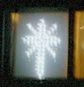

STAR-CROSSThis circuit uses the two halves of a H2 dual half-wave string or two H1 half-wave strings to produce two flashing effects in the same pattern. It can also be used to make two sets of straight-line H1 lights intertwined together produce an interesting flashing effect. In the Star-Cross pattern shown, one of the half-wave series lights the vertical and horizontal arms of the cross. The other half-wave series lights the diagonal rays and the lights at the tips and center of the pattern. This produces a pleasing twinkling star effect. Each of the half-wave series can be off, half bright, or fully bright, giving 9 different instantaneous displays. This can also be used with the F1, F2, B1, and D1 strings to light a single string with 6 different shimmer brightness levels (including off). It can also supply both H strings and F strings to produce an even more interesting combination of blinking and shimmering. The animated view at right shows how it behaves. STAR-FLAKEThis circuit was formerly used to light the same pattern (above), and later, an F1 full-wave string in the shape of a 5-pointed star with snowflake patterns around it. It provides a shimmering effect with the Star-Cross string, or causes the Start-Flake to shimmer to 3 different brightness levels. |
|
||||||||||||
SEQUENCERS
Sequencers are fun. They can be used to animate any display. The swinging bell display shown here uses a 1|2|3|2| oscillating pattern (Osc 3 below) that sequences three different images to produce the effect. Sequencers have three different kinds of components:
Many sequences are possible. Only the counter upper limit and the number of decoder drivers limit your choices. Here are some useful sample sequences, with sample displays, shown in the order seen in the diagram on the right:
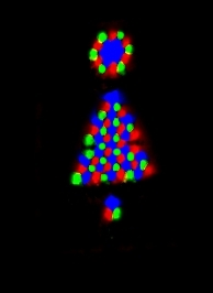
The colors shown are based on the lamp drivers having these colors plugged in the drivers: 1=red, 2=green, 3=blue, 4=white Use your imagination to devise different kinds of displays to use these sequencer patterns. They can be chase lights running around a room, animated cartoons doing various things (e.g. the bell above), rotating stars (as in the examples), color changing effects (as in the examples - using different colored strings), lighting the tree panel at right, or even simulating one of those 1960s color wheels (using 3 or 4 different colored floodlights). |
The diodes are small signal diodes with PRV larger than 15 V. They let any number of counter outputs work a single lamp driver. The 9 V supply is a 9 V battery replacement wall transformer. Choose the triacs to match the load you have. Switches can be interposed between the diodes and the 24 K resistors to make the same lamp drivers use different sequences. Since line voltages are present, build all of these to National Electrical Code requirements. |
||||||||||||
USE OF A GE GALA CONTROLLER WITH LEDS
Use wiring diagrams at right:
To extend LED string life, use wiring diagram type F at right:
|
Selecting the load type for the GALA unit by string type:
Values are for one 20 mA string per GALA output. The GALA unit is doing a Spin 4 pattern in the animation at left. |
||||||||||||
|
BUILD A CONVERTER-DRIVER
Use the wiring diagram at right:
|
This circuit works with most kinds of special light control devices. This circuit can be built to drive loads much larger than the special devices can drive. This circuit provides electrical isolation between the special device and the load circuit. Since line voltages are present, build all of these to National Electrical Code requirements. The plug on the left is 2-prong to fit any kind of special device. |
||||||||||||