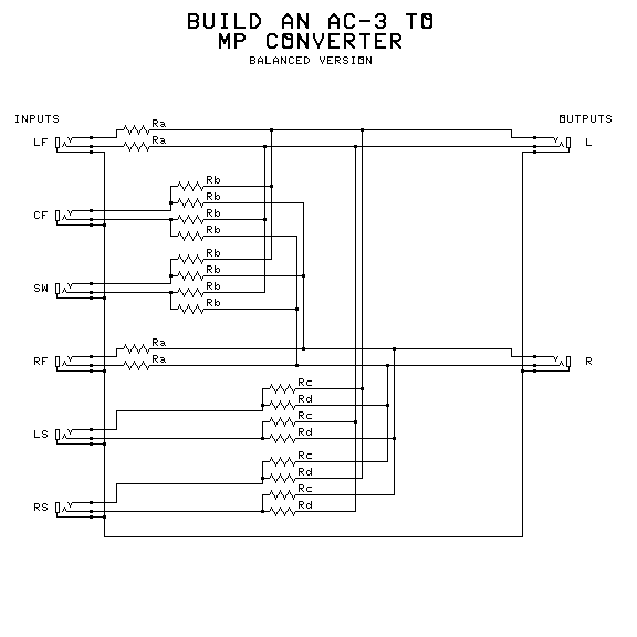
Balanced Converter

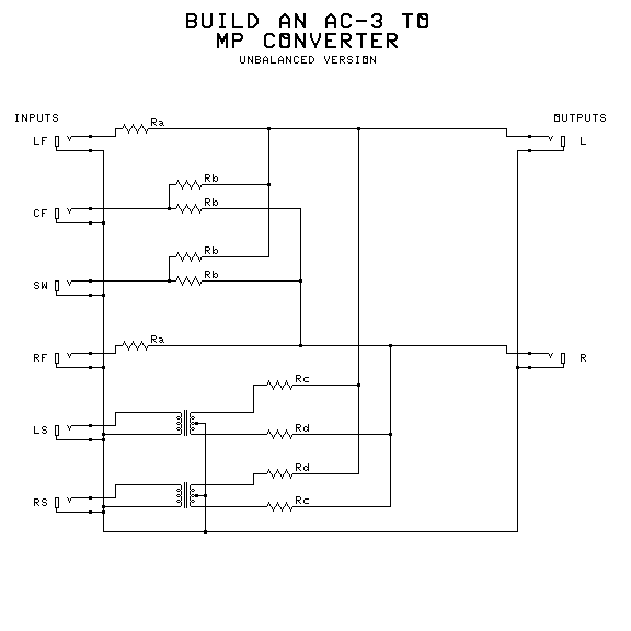
Unbalanced Converter
Something isn't quite right. You have a new source that puts out the new AC-3 (or other 5.1 channel surround), but your transmission (or output) device inputs only take two channels. The manual says to connect the Left output to the Left input of your device and the Right output to your device's Right input. But something is wrong: The dialog of most movies comes out at very low levels, and there is no surround information at all. The source has no mode selector to allow you to choose a composite signal. What do you do?
Build my AC-3 to MP converter:
You can choose two different methods of encoding. In one design, both of the surround channels are encoded identically, placed at center back. Any separation between them is lost, but the localization of sounds in other directions is improved. The other method preserves some separation between the surround channels, but can degrade localization of sounds that are more forward on either side.
You have three choices of the method of construction: Choose the one that best fits your application and budget.
- You can choose the balanced version, for professional applications with balanced line signals. Balanced line reduces hum and noise pickup, and is a must for noisy environments. Do not feed unbalanced signals to the surround inputs or feed the output to unbalanced devices without using direct boxes to convert the signals to balanced line.
- You can choose the unbalanced version, for equipment that can't use or provide balanced line. Home uses need the unbalanced version.
- If you have an unused mixer handy (or need this temporarily) you can use the method outlined in Encoding Surround Sound with your Mixer on this website.
IMPEDANCE SELECTION AND RESISTOR VALUES
Balanced line signals usually have 200 to 600 ohm impedances. Select 600 ohms as the value of Ra to start with. Then choose the other values according to what levels you need and the load impedance of your transmission or output device.
Some unbalanced lines use low impedances in the range of 200 to 600 ohms. If this is the case, use the values presented above for balanced line.
Other unbalanced line signals have 2000 to 18000 ohm impedances. Select 10000 ohms as the value of Ra to start with. Then choose the other values according to what levels you need and the load impedance of your transmission or output device. Home equipment is usually in this range, although older tube equipment may have higher impedances.
One suggestion is to use trimpots for the resistors. Then they can be readjusted if a different output device is needed. If trimpots are used, make sure that all of them with the same designation (example: Rb) are adjusted identically. One trick for doing this is:
- Use identical trimpots for all of the resistors.
- Make sure the trimpots are mounted where meter probes can get to their terminals.
- Leave the unused terminal of each trimpot unconnected.
- Set one of the trimpots for the desired result.
- Measure the resistance between the free third terminal and the slider.
- Adjust each of others with the same designation for the same value between the free terminal and the slider.
Another suggestion is to connect a load resistor across each balanced output, or from each unbalanced output to ground. These could also be trimpots.
The following is a good guide to value selections:
- Identical surround channel encoding:
- Rb = 2 Ra
- Rc = 2 Ra
- Rd = 2 Ra
- Separated surround channel encoding:
- Rb = 2 Ra
- Rc = 1.8 Ra
- Rd = 3 Ra
A switching arrangement could be used to select the method.
The transformers are 1:1 isolation transformers, and are selected to match the impedance used.
Different connectors may be substituted as needed:
- The top terminal shown on each phone jack drawn is the tip. The bottom terminal is the sleeve, and the middle one (if used) is the ring.
- Grounding arrangements can be modified to take care of ground loops.
- XLR connectors are wired with pin 2 connected to the top wire (tip) drawn at each shown phone jack, and pin 3 (the middle one) connected to the middle wire (ring) drawn at each phone jack. The sleeve connection (ground) goes to pin 1.
- RCA phono jacks may be used with the unbalanced version only. Connect the pin to the tip wire, and the sleeve to the sleeve wire (ground).
- Other connectors can be used to match available cables or equipment.
- Direct boxes may be used to produce balanced line signals or use them.
ENCODING WITH A MIXER:
Use the following settings to encode the 6 channels into the 2 used with MP:
- For identical surround:
- Left Front: Select the front half, and pan almost all the way left.
- Center Front: Select the front half, and pan to center.
- Right Front: Select the front half, and pan almost all the way right.
- Left Surround: Select the back half, and pan to center.
- Right Surround: Select the back half, and pan to center.
- Subwoofer: Select the front half, and pan to center.
- For separated surround:
- Left Front: Select the front half, and pan almost all the way left.
- Center Front: Select the front half, and pan to center.
- Right Front: Select the front half, and pan almost all the way right.
- Left Surround: Select the back half, and pan about 1/3 to the left.
- Right Surround: Select the back half, and pan about 1/3 to the right.
- Subwoofer: Select the front half, and pan to center.
- Additional processing for best results:
- Left Surround and Right Surround: Use a low pass filter that removes frequencies above 7 KHz on the signal entering this encoder.
- Subwoofer: Use a low pass filter that removes frequencies above 100 Hz on the signal entering this encoder.
Once this is adjusted, it should need no further attention.